We understand that this is a tough time for all. If you have any questions or concerns, please reach out to the teaching staff.
Looking back
During the course of the semester, we have learned about different aspects of building robotics systems:
- Basics of ROS Development and Tools
- State representation
- Communication protocols
- Sensors and error correction
- Programming deployments
- Environment perception
- PID controllers
- Testing robots
- Mapping and motion Planning
- Transforming coordinate frames
We will use many of these skills to develop a robot system in teams of up to 2 people that is capable of performing a complex task autonomously.
Motivation
Robots are well suited for many jobs that may not be a good fit for humans. We want to protect humans from dangerous jobs that can be carried out by expendable robots. Repetitive tasks can be automated for robots; robots can have better endurance and we can build actuators and joints that are well suited for repetitive motion where human joints are not. Similarly, dirty tasks can be performed by robots that can work in a wide range of environments that are not friendly to humans.
For this project, we will be developing a robot for a dangerous and dirty task: attempting to perform a search and rescue mission for a lost dog in a collapsed building.
Trapped in a collapsed building
There has been a natural disaster that has caused a large building to collapse. Because of the collapse, the internal structure of the building is uncertain, and it is not safe to send in a human to explore the area. There is a dog trapped inside the building with an wireless collar that has initiated a call for help. The dog is in no immediate danger, but given the uncertain state of the building, it needs to be rescued as soon as possible. In the collapse, the building’s security system has shutdown all of the doors and all of the other exits are blocked. By triangulating the signal of the collar, the first responders are able to estimate the dog’s position in the Cellphone Tower’s frame of reference.
A rescue crew is standing by to be able to evacuate the dog, but they need your drone to enter the building through one of the ventilation shafts, explore the area to find a path to the dog, and open all of the security doors along the way.
In the collapse, the lights have failed and so camera systems will not work. Instead, your drone is equipped with a 360 degree LIDAR that can determine the locations of obstacles. In addition, your drone has been equipped with an arm that can use a key to manually override the security doors, along with a limited number of keys. The building architects tell you that the doors are made of a very different material than the rest of the building, and that your LIDAR should be able to pick up the difference between the door and the other obstacles.
Your drone will start at the exit of the ventilation shaft in the center of the building and must navigate through the building to find the trapped dog. Along the way, it must open all of the doors along the path to the dog, and generate a map of the area around the path to the dog. The mission is successfully completed once the drone has reached the dog; the drone will relay all of the information out and wait with the dog for help to arrive.
Mission Specifications
Your main objective is to build a system to safely navigate your drone in the uncertain environment, open all of the doors, and find the trapped dog.
To achieve your mission, you must:
- Access the Cellphone Tower data to get the dog’s last known location.
- Safely navigate around the unknown obstacles to reach the dog
- Never crash into an obstacle; if your drone crashes into an obstacle, the GUI will freeze and the terminal will print a crash message until you stop the program.
- You must use the LIDAR system to develop a map of the area and avoid obstacles.
- Develop a global planner to generate a path that explores the map to find a path to the trapped dog
- Managing doors
- As you explore the map, you must open any doors that you find to clear the way for the rescue team to come behind you.
- The doors will appear differently in the LIDAR readings as the LIDAR is much more noisy when looking at a door. All of the LIDAR readings have noise, but LIDAR points on a door have 10 times the baseline level of noise.
- During your mapping, you should note where these doors are and whether they have been opened.
- Careful! You have a limited number of keys, and each key can only be used once. Each time you attempt to open a door, a key is used up regardless of if the door was successfully opened.
Project Setup
At the end of the project, you will submit a zipped copy of your simple_control folder which must contain all of your code for the project. You may only edit files in this package.
The project builds off of the previous labs, but leaves much more room for you to implement and make your own design decisions. Instead of providing partial source code with labelled TODOs, we outline the data available to you and loosely describe where you should implement the remaining portions of the project.
To retrieve the new code base for the final project, run:
cd ~/CS4501-Labs
git pull
Nodes and Topics Provided
You may not edit any of the code provided by the teaching staff. Your final submission must work with the originally provided teaching staff code. Solutions that do not conform to this specification will receive NO CREDIT.
All of the mission logic from the teaching staff has been combined into the environment_controller node.
This node tracks the state of the world throughout the mission, simulates the LIDAR, and is responsible for the environment and opening the doors when commanded.
If the drone has completed the mission without crashing, a success message is published containing the time taken to complete this run.
Only the following topics may be used to interface with the teaching staff code. You may not use any additional information. You are allowed to create any topics, etc. you need in the simple_control package to communicate between your code.
| Topic | Text Description | Your task |
|---|---|---|
/cell_tower/position |
The dog’s last known position in the cell_tower frame |
Transform into world frame and navigate |
| TF Transforms | Provides a transform lookup between coordinate frames in the system | Lookup the cell_tower to world transform |
/uav/sensors/lidar |
The LIDAR reading from the 360 degree lidar | Identify the obstacles and doors during navigation |
/uav/sensors/gps |
The GPS position of the drone | Use this information for localization and planning |
/keys_remaining |
The number of keys that the drone has left to use. | The drone always starts with 4 keys and each call to the use_key service uses up one key. |
| Service | Text Description | Input | Output | Your task |
|---|---|---|---|---|
use_key |
When your drone is within 1 meter of a door, use this service to attempt to open the door | The geometry_msgs/Point of the door in the world frame |
a bool noting whether a door was opened or not |
Invoke this service as needed to open any doors along your path |
Your responsibilities
| Topic to publish | Type | Text Description |
|---|---|---|
/map |
nav_msgs/OccupancyGrid |
The occupancy grid must contain your current estimate of the map of the building. The values should range from 0 (fully confident cell is free space) to 100 (fully confident cell contains an obstacle). The special values -1 and -2 may be used to mark closed and opened doors respectively. The value -3 may be used to mark the goal. |
/uav/final_path |
std_msgs/Int32MultiArray |
Once the drone has completed the mission, it must publish the shortest path between its starting position and the dog’s position |
/uav/input/position |
geometry_msgs/Vector3 |
Use the global/local planner to command the drone’s next movement |
/uav/path |
std_msgs/Int32MultiArray |
This is not required. Paths published on this topic will be shown in the GUI. Visualizing the planned path of the drone can be useful for debugging. |
You may publish these messages at any rate that you wish; however, the GUI updates at a rate of 5Hz.
One possible design could use the following:
- A global planning capability that is responsible for generating paths to positions in the map
- A local planning capability that is reponsible for ensuring that the current path will not lead to collisions
- A mission planner that is responsible for determining which actions to take and for keeping track of the state of the system.
Global Planner
The purpose of the global_planner is to plan a path to a goal.
This planning must be done in a way that is cognizant of the unknown map and explore in order to find the dog.
You may implement the global planner however you like, using what you’ve learned from the previous labs.
Local Planner
The purpose of the local_planner is to avoid obstacles that are not yet on the map.
The exact behavior will depend on your implementation of the global planner; however, the local planner must act as a runtime monitor to monitor for imminent collisions and prevent them.
You may implement this however you like, using what you’ve learned from previous labs.
Mission Planner
The purpose of the mission_planner is to keep track of the state of the mission and make decisions about what actions to take.
This should keep track of the number of keys remaining, facilitate using the keys to open the doors, etc.
Logistics
The environment is randomly generated on startup. This randomness is controlled by the seed parameter in flight_controller/fly.launch. When debugging your code, you may find it helpful to use the same random seed multiple times. However, you should verify that your system works for many different choices of random seed. We have included several examples in the tips section below.
Similarly, the map size is controlled using the map_width and map_height arguments. These arguments are passed to the simple_control/simple_control.launch file where you can then pass the data into your code.
As the map gets larger, it may take your system longer to successfully complete the mission. Due to the variation of the maps and possible choices for exploring the map, there is no single time limit. However, we have given some guidelines on how long it takes the teaching staff solution to solve different maps below; when grading your solutions, the timeout will be set to no less than double the teaching staff runtime. As noted in the evaluation section below, the fastest solution in the class will receive 1 point (5% of the project grade) of extra credit.
During grading, you must show your implementation working on at least a 23 by 23 map.
Your solution should make no assumptions about the map size or obstacle placement. During grading, the teaching staff will run your solution on many different map configurations and seeds.
Tips to get started
Your final solution will give you a taste of what implementing a full complex solution to a real world problem would entail. The complexity introduced by multiple people working on different parts of the solution, the different parts of the solutions having different and unique functions, as well as integrating many different pieces of software all make the complexity of the problem an increasing difficult challenge.
Control States
One way to manage this complexity is through finite state machines which were introduced in Lab 3. You might consider using one to handle the different states. Different states you might consider including are:
- Exploring World
- Locating Doors
- Opening Doors
- Moving to Waypoint
- Updating Map
This list continues, but the point is this will help manage your code and keep it easy to read and debug.
Occupancy Grids
As we learned about in Lecture 7, occupancy grids are a useful data structure for representing the environment.
The grid provides both a mechanism for storing information about obstacles and a useful framework for implementing path planning algorithms, such as how we used A* in Lab 7.
In Lab 7, we learned about using images and yaml files to store map data and using the map_server to make these accessible in ROS. The data that we included in these files closely aligned with the ROS OccupancyGrid message type, which is what the map_server used behind the scenes.
In this project, you must use an OccupancyGrid object to publish your current understanding of the obstacles in the world. The GUI code has been programmed to visualize the data on a scale from 0 to 100, representing how confident you are that there are or are not obstacles in a given grid square. A value of 0 means that you are completely confident the square is empty, and a value of 100 means you are completely confident the square is occupied.
Given that you initially have no information about the world, you should initialize your OccupancyGrid to have values of 50 (equally unsure about occupied or unoccupied) for all squares. Then, as you explore the map, you can update the squares with the new information. As you get new readings from the LIDAR, you know more about whether a given square is occupied or unoccupied.
Each beam of the LIDAR reports the distance to an obstacle at that point, or infinite if there was no obstacle detected within the maximum range of the LIDAR.
This means that, up to the maximum range of the LIDAR, you know whether every square between the drone, where the LIDAR originates, and the point the LIDAR hit, is unoccupied. Additionally, you know that the square where the LIDAR beam hit an obstacle is occupied.
Thus, for each individual LIDAR scan we receive, we can build a list of grid squares that we think are unoccupied, and a list of grid squares that we think are occupied.
However, LIDAR is noisy, and so in general we do not want to trust a single LIDAR reading to know the state of the grid. Instead, we use this to update how confident we are that a given grid square is occupied.
Every time we receive a LIDAR scan, we generate a list of occupied and unoccupied squares. Then, for each of those squares, we either increase or decrease the value of that grid square in the OccupancyGrid to indicate that we are more or less sure that the square is occupied.
When path planning, we need to know for sure whether we can treat a grid square as unoccupied, i.e. can the drone try to navigate to that square. As such, we generally set a threshold for how confident we must be that a cell is open. How you determine how much to alter your confidence of individual squares each time you get a new scan and how you set the threshold to determine if a square unoccupied are up to you.
The animation below visualizes an occupancy grid discovered by a robot, by Daniel Moriarty: Link
Special values in the OccupancyGrid
Normally, OccupancyGrid message types only contain positive data indicating the confidence level of occupancy. However, for this project we have extended the functionality with a few additional flags. You can use the value -1 to indicate a closed door, the value -2 to indicate an opened door, and the value -3 to represent the goal. This can greatly aid in your debugging process.
Converting Between Occupancy Grids and the Continuous World.
Our drone operates in a continuous world. The drone starts in the middle of the world at position (0,0). The map you will be building operates in a discretized world. This adds two complexities which you need to consider.
First the map frame’s origin is at the bottom left of the map. So for example, when you reference map cell [0,0], you will be referring to the cell in the bottom left. However, when you refer to the drone’s position [0,0], you are referring to the exact center of the map. This is because the drone operates in the world frame.
Second, when you refer to a cell (for example, cell [0,0]), you are referring to the center of an entire 1x1-meter cell that covers the square in the world frame from the point (-0.5,-0.5) from the map offset all the way to the point (0.5,0.5) from the map offset.
Service Calls
Opening the door is implemented as a service. This is because we need to know whether the door was successfully opened or not. Services, as we learned in Lab 3, work in a synchronous manner. That is, they return a message after being called by a client. Remember the syntax on how to call the service use_key can be found by looking at the ROS wiki (http://wiki.ros.org/ROS/Tutorials/WritingServiceClient%28python%29)
Simplifying assumptions
- The drone will always start at (0, 0) and that will be an unoccupied square.
- All obstacles are exactly 1 meter by 1 meter in size
- There is a unique shortest path between the start and the goal
- There are always exactly 3 doors, and they are always along the shortest path between the start and the goal
- The square behind a door will always be open
- Doors will only appear at an odd manhattan distance from the goal.
- The dog will never move, and the transformation between the
cell_towerandworldwill never change. - For the purposes of LiDAR readings, you may assume that the roll, pitch, and yaw of the drone are 0.
- Except for “intersections”, all “hallways” will always be one wide; more concretely, there will never be a 2x2 block of open cells.
- The world may not be square, but each side will be no more than 31 cells in length.
- The outer boundary of the map will always be obstacles.
Example Seeds
Here we provide the complete maps for several possible map configurations and seeds. These can be useful when debugging as they provided controlled environments where you know the expected output. Additionally, for any seed, the system will output an ASCII art drawing of the map to the terminal after ROS has shutdown.
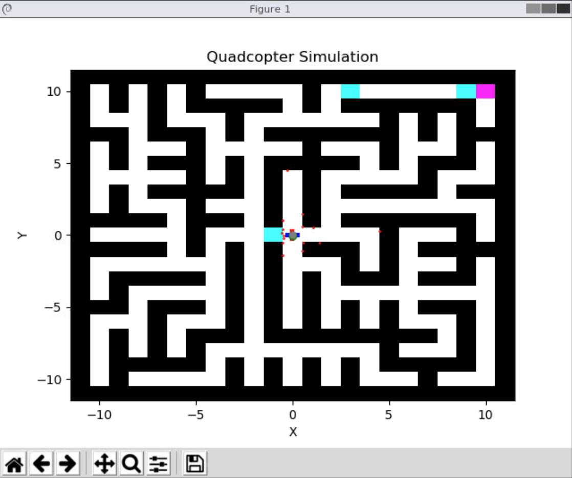
Example 1:
There is a door directly adjacent to the starting position. This is particularly useful because it allows you to develop your door detection without implementing any navigation or occupancy grid detection code.
  <arg name="map_width" default="11" />
  <arg name="map_height" default="11" />
  <arg name="seed" default="6" />
Teaching staff solution runtime: 41.1 seconds
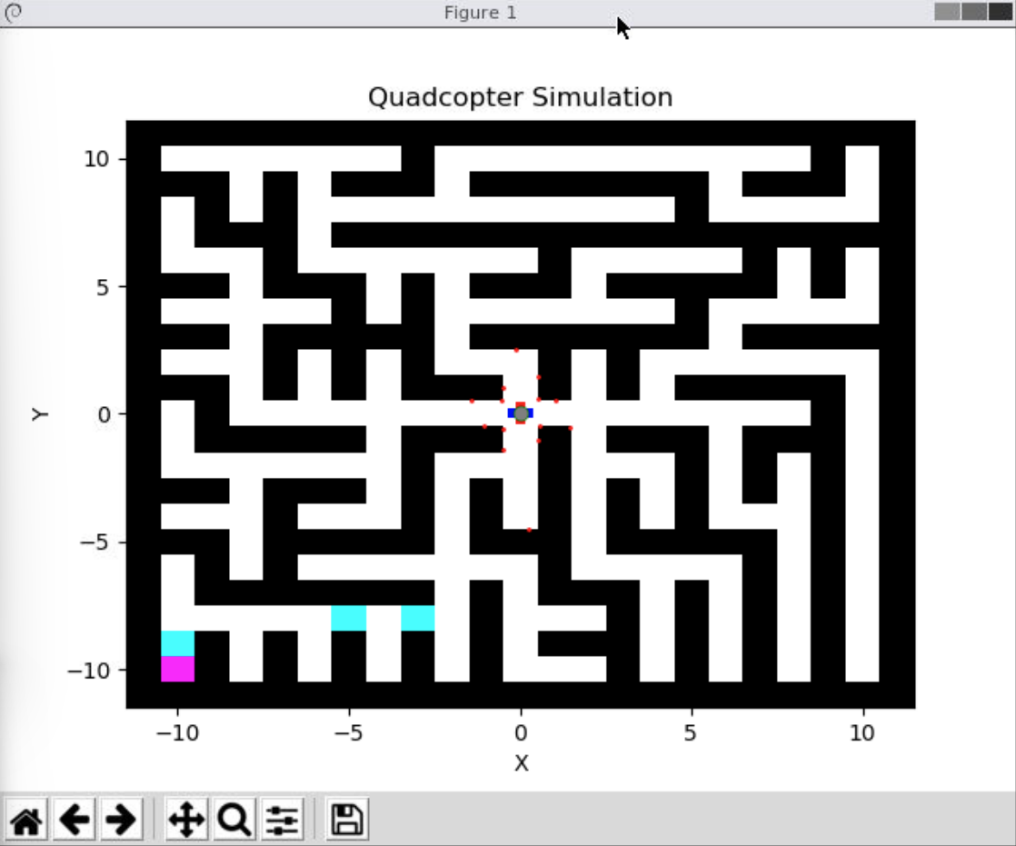
Example 2:
A generic 11 by 11 map. This map is small, to allow for quick debugging in a controlled environment.
  <arg name="map_width" default="11" />
  <arg name="map_height" default="11" />
  <arg name="seed" default=3" />
Teaching staff solution runtime: 42.8 seconds
Additionally, the below is a video of solution to this scenario (sped up 5.5x).
Example 3:
Your solution should not make any assumptions about the map dimensions. This provides an example case where the map is not square.
  <arg name="map_width" default="31" />
  <arg name="map_height" default="15" />
  <arg name="seed" default="35" />
Teaching staff solution runtime: 154.9 seconds
Example 4:
During grading, you will be asked to demo a map that is at least 23 by 23 in size. This provides a simple test case for that scenario, again where the door is directly adjacent to the starting position.
  <arg name="map_width" default="23" />
  <arg name="map_height" default="23" />
  <arg name="seed" default="107" />
Teaching staff solution runtime: 336.3 seconds
Example 5:
Another 23x23 example. In this case, there is a door directly in front of the goal.
  <arg name="map_width" default="23" />
  <arg name="map_height" default="23" />
  <arg name="seed" default="100" />
Teaching staff solution runtime: 139.8 seconds
Project Evaluation
Your project will be evaluated on its ability to meet the following requirements.
- The drone must never collide with an obstacle (Automatically detected)
- The drone must reach the dog’s location (Automatically detected)
- The drone must report the shortest path between its starting location and the dog once found (Automatically detected)
There are two milestones for the project: an in class demo and a final code submission.
In class demos will be held on Wednesday, November 30th.
The final code submission of your zipped simple_control package is due Tuesday, December 6th through Collab. Only one team member should submit. Make sure that both team members’ names are in the simple_control.launch file.
Late submissions will be deducted 25% per day late for the final submission.
The final project is worth 20% of your class grade. The grading breakdown is:
- 8 points for the in-class demo
- The in-class demonstration must show the drone completing two of the subtasks (4 points each): opening a door and generating the map.
- For opening the door, you may use one of the seeds above where the drone starts adjacent to the door. Show that your drone can open that door. For the final submission your drone must be able to automatically detect and open doors; however, for this demonstration, the location of the door can be hard-coded.
- For generating the map, show that your solution can build an initial occupancy grid showing the status of the location around the starting position; the drone does not have to move. For example, in the GIF shown in example 2, the drone starts up and identifies the area around the start before it begins moving.
- While we will aim for live demos, you should come prepared with a video recording as well.
- The in-class demonstration must show the drone completing two of the subtasks (4 points each): opening a door and generating the map.
- 12 points for the code and video submission through Collab
- Submit a video of the drone completing 3 different scenarios of size 23x23 that are not shown above.
- The code submission will be graded against a suite of scenarios that the teaching staff choose, each of which must pass.
- 1 Extra Credit point for the fastest solution time in the class on a hidden map chosen by the teaching staff
We understand that this is a tough time for all. If you have any questions or concerns, please reach out to the teaching staff.
Congratulations, you are done with the final project and CS4501: Software Engineering for Robotics!