At the end of the test you might get an error which states: ROSException: publish() to a closed topic. This is normal and might occur depending on the order nodes where shutdown by rostest. It should not affect the success or failure of your tests.
PID Controllers and Rostest
A PID Controller is an algorithm that uses the error between a setpoint and a measurement to adjust the system’s output with the goal of maintaining the set point. A PID relies on three terms (P,I,D) to control the system output to minimize the error. PIDs’ broad applicability and popularity in robotics makes them worth their own lab.
Learning Objectives
In this lab, we will implement and test a PID controller. At the end of this lab, you should be able to:
- Implement a PID following system-level requirements
- Understand the role of each term in a PID and how to set them
- Use the ROS testing framework rostest to implement system tests
Overall Scenario for the Lab
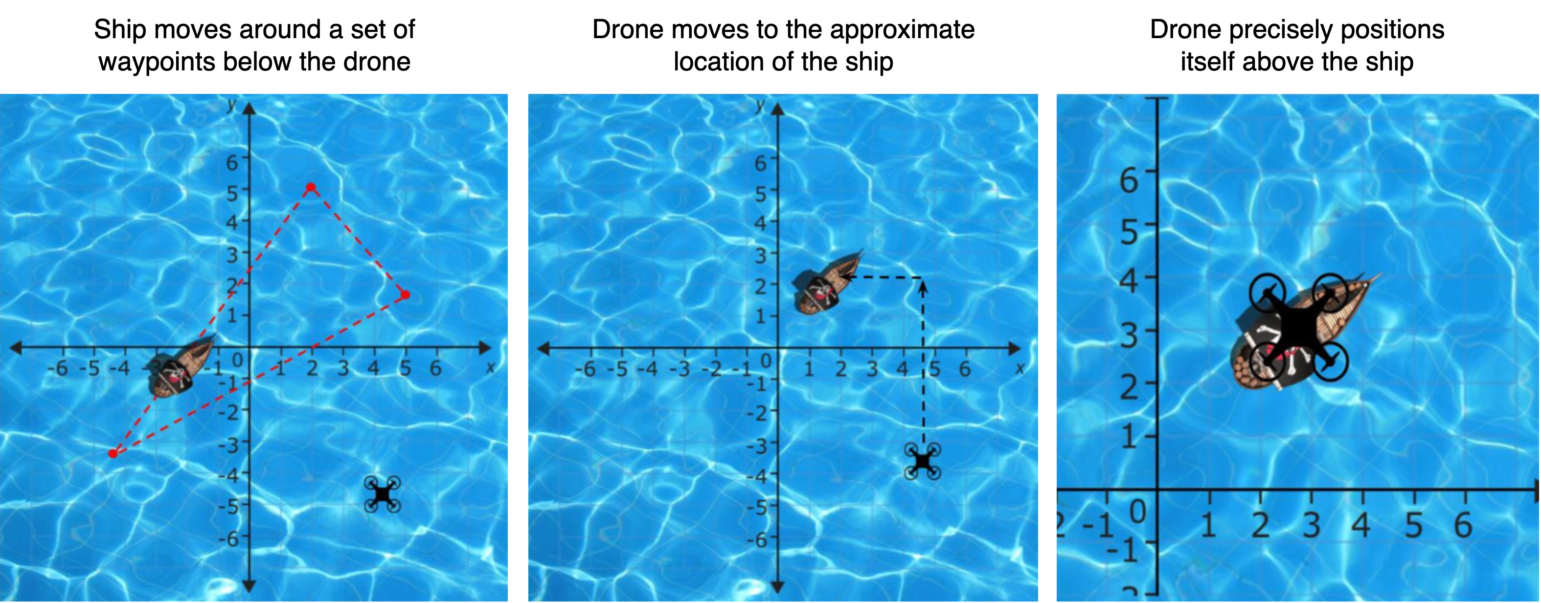
In this lab, we will be developing a drone subsystem, ship_following_controller, that attempts to position the drone on top of a moving ship at sea.
The drone will first head toward a ship’s approximate location using the ship’s beacon. Then, when the drone is within a certain distance from the ship, it will pick up a second beacon, thereby giving a more precise distance to the ship. The drone will adjust its position using its PID controller and these two beacons to be centered on top of the ship. Note that there is no drone camera visualization for this lab, as it is too computationally expensive.
Lab Requirements
Retrieve the new code base for Lab 6 by navigating to your CS4501-Labs directory and running git pull.
Requirements for Ship Follower - ship_following_controller
As mentioned earlier, the goal of the ship_following_controller node is to position your drone over a ship.
The positioning requires three steps:
- Climb to an altitude of 9 meters - this height is required for the beacons to function.
- Move the drone to the approximate x, y coordinates of the ship, using the
/ship/beacon1topic. Then, use the/ship/beacon2topic to precisely position the drone over the ship. Note that/ship/beacon2will only appear when your drone is close to the ship. - Use well-tuned PID controllers (x and y will share one set of PID values, but have two separate instances for their velocities, and z will have its own set of PID values and its own instance velocity) to position the drone above of the ship.
Once the node is implemented and the PIDs are fully tuned, the drone should be able to follow the ship without losing connectivity with /ship/beacon2.
Unlike previous labs, we will be publishing to /uav/input/velocityPID to fly the drone.
The node must publish to the topic /uav/input/velocityPID at a rate that can keep up with the ship’s speed.
Inputs required:
The ship_following_controller node subscribes to:
/uav/sensors/gps, which contains the x,y,z values for the position of the drone. You may only use the Z values./ship/beacon1, which gives a coarse estimate of the relative location of the ship/ship/beacon2, which gives a more precise estimate of the relative location of the ship once the drone is in range
Configuration parameters required:
The node must read the following parameters from the parameter server for the PIDs: the proportional constants pxy and pz, the integral constants ixy and iz, and the derivative constants dxy and dz. Those parameters must be part of the relevant launch file.
The Ship Node - ship
The ship_following_controller node retrieves a lot of its information from the ship node (found in the sensor_simulation package). We will be using the ship node to test ship_following_controller. For this reason, it is worth understanding some of its operations.
The ship node is configurable via two parameters: ship_velocity and ship_waypoints.
ship_waypoints determines the waypoints that the ship visits as it navigates around the x,y plane of the ocean. Once it reaches the end of the series of waypoints, it returns to the first waypoint. If it is given a single waypoint, it idles at that waypoint. ship_velocity sets the velocity with which the ship travels between waypoints, in units per second. For testing, it has been constrained to values between 0.0 and 1.0.
The topic /ship/beacon1 provides a set of coarse x, y directed vectors of the drone to the ship.
The vectors treat the drone as the origin and the ship as the endpoint.
However, the ship measures distance using different units than the drone, so the PIDs must be tuned to reflect that.
The topic /ship/beacon2 functions similarly, except it only publishes when the drone is nearby the ship and uses different units from the drone and from beacon1 to give a greater precision. This needs to be taken into account when tuning the PIDs and integrating the two error terms provided by /ship/beacon1 and /ship/beacon2. You are welcome to use the two beacon values in any way you wish. You may consider using one or the other depending on the situation the drone is in, or fusing them into one error sensor. Be sure you can explain how and why you used them in the manner you did.
The ship publishes its topics at a rate of 4Hz.
Developing ship_following_controller
We will now write the code to implement all the requirements outlined above for ship_following_controller. Afterwards, we will incrementally tune each term of the PID and run the relevant test cases to show that the requirements are met.
The ship node simulates data that would be generated by a ship, including broadcasting to other entities. The location data published by ship are then used by your ship_following_controller node to produce control inputs for your velocity controller.
The skeleton code is provided in simple_control/src/ship_following_controller.py:
#!/usr/bin/env python
import rospy
import time
import math
import numpy as np
from threading import Lock

from geometry_msgs.msg import Vector3, PoseStamped, TwistStamped, Vector3Stamped
from std_msgs.msg import String, Bool, Float64
from sensor_msgs.msg import Image
from sensor_msgs.msg import Image
from cv_bridge import CvBridge

from velocity_pid_class import PID

# A class used to follow ship below drone
class ShipFollower():
  # On node initialization
  def __init__(self):

    # Allow the simulator to start
    time.sleep(3)

    # When this node shutsdown
    rospy.on_shutdown(self.shutdown_sequence)

    # TODO: Retrieve rate from ROS params

    self.dt = 1.0 / self.rate


    # TODO: Retrieve the PID parameters from ROS parameters


    # TODO: Initialize PIDs with PID class and ROS parameters


    # TODO: Initialize zero'ed class vars
    self.gps_height = 0

    # TODO: Create the publishers and subscribers

    # Run the control loop
    self.ControlLoop()

  # TODO FOR CHECKPOINT 1
  def get_gps(self, msg):
    # ONLY SAVE THE HEIGHT
    pass

  # TODO FOR CHECKPOINT 2
  # callback for /ship/beacon1
  def get_ship_beacon1(self, msg):
    pass

  # TODO FOR CHECKPOINT 2
  # callback for /ship/beacon2
  def get_ship_beacon2(self, msg):
    pass

  # TODO FOR CHECKPOINT 3
  # combine PID output from the two beacons
  # You don't have to use this method,
  # but you will need to use both error terms
  def combine_beacons(self):
    pass

  # This is the main loop of this class
  def ControlLoop(self):
    # Set the rate
    rate = rospy.Rate(self.rate)

    # While running
    while not rospy.is_shutdown():
      # Use PIDs to calculate the velocities you want
      # TODO FOR CHECKPOINT 1: z velocity

      # TODO FOR CHECKPOINT 2: x and y velocity
      # Sleep any excess time
      rate.sleep()

  # Called on ROS shutdown
  def shutdown_sequence(self):
    rospy.loginfo(str(rospy.get_name()) + ": Shutting Down")


if __name__ == '__main__':
  rospy.init_node('ship_follower_node')
  try:
    ktp = ShipFollower()
  except rospy.ROSInterruptException:
    pass
To implement your PIDs, skeleton code for a reusable PID class is provided in velocity_pid_class.py.
#!/usr/bin/env python

class PID:
  # TODO FOR CHECKPOINT 0
  # On node initialization
  def __init__(self, p=0.0, i=0.0, d=0.0):
    pass

   # TODO FOR CHECKPOINT 0
  def pid_loop(self, error, dt):
    pass
Add the ship_following_controller to the fly.launch file, along with ROS parameters for PID constants and the rate.
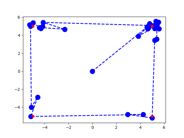
A script has been provided for you in src/simple_control/src/debug_pid.py to visualize the behavior of your PID as it traverses four waypoints arranged in a square. The output of this script is shown below. The red dots show the expected waypoints, while the blue dots show the drone’s position at set time intervals. You can see how the drone would traverse by looking at the blue dotted lines.
This is an opportunity for you to tune a PID in a simplified (but still noisy) environment and see some of the behaviors that certain kinds of tuning produce (overshoot, oscillation, etc.). Feel free to change the waypoint configuration or dt of the PID loop to figure out how your PID approaches setpoints, but keep in mind that the tuning for this PID is not necessarily going to translate to your drone. The purpose of this script is for you to be able to test your PID implementation independent of the rest of the system and gain a general understanding of what PID behavior looks like as it relates to its tuning.
Another aspect of your PID that you can test with debug_pid.py is the fact that PIDs are unit-agnostic.
This is incorporated as an aspect of tuning. To test this, modify the x_err and y_err fed to the PID by a ratio of your choosing.
Checkpoint 0
You do not need to turn anything in for this checkpoint, but before continuing, ensure that you can use your PID implementation to reach all of the waypoints in debug_pid.py.
A PID Controller for Hovering
As discussed above, the drone must be at a height of at least 9 meters for the beacons to function correctly. You will implement a PID controller for the z-velocity to ensure that the drone stays above the required height.
NOTE: because you have not yet implemented a PID for x and y directional control, your drone may float around the map as it is hovering; this is okay.
Checkpoint 1
- Set up a P controller for the z-velocity in
ship_following_controller.py. - Use
rqt_plotandrostopic echoto show that your drone can hover consistently above 9 meters. Take a screenshot showing this behavior.
What Should We Test and How Should We Test it?
Once you have implemented the z-velocity controller, implement the x and y velocity controller.
Note that the drone is a complex system that controls its movements through the 4 rotors. Because of this, it cannot act independently in the x, y, and z dimensions, meaning that each of your PID controllers for x, y, and z will affect each other. While we asked you to only implement a P controller for Checkpoint 1, you will likely need to tune your Z controller to include other parameters to work well with the X and Y PID controllers.
After those are implemented comes the time to check if it all works according to the requirements.
For Checkpoint 1, we used rqt_plot to manually verify that our PID controller was meeting our requirements.
In Labs 4 and 5, we checked the correctness of the classes we developed using unit test with Python unittest.
For testing classes or groups of classes that rely on ROS, such as those nodes subscribing and publishing, we need to integrate the tests within rostest.
Rostest provides you with a wide range of built-in capabilities to test your code.
For example, rostest includes a family of predefined tests.
For example, hztest checks that topics are published at the correct frequency, paramtest checks that parameters are set correctly, and publishtest checks if specific topics are published at least once. In addition to the non-functional tests, rostest allows you to create custom test classes that can be tailored to your specific application.
We have developed a few such test cases for you in the system_tests package. These tests will run the system and validate that the communication between nodes and node integration works as expected, and you will develop similar tests to check your ship_following_controller node.
Configure rostest
Rostest is already installed in your Docker container. To signal to catkin that the package system_tests contains rostests, we have made some changes to its package.xml and CMakeLists.txt. To package.xml of the system_tests package we added the line:
<test_depend>rostest</test_depend>
This indicates that your tests rely on the package rostest. To CMakeLists.txt of the system_test package we added the lines:
find_package(rostest REQUIRED)

add_rostest(launch/hz_test.launch)
add_rostest(launch/param_test.launch)
add_rostest(launch/test_hovering.launch)
Recall that the CMakeLists.txt tells catkin how to build your ROS code. By adding these lines, you indicate to catkin that it should compile the tests hz_test.launch, param_test.launch, and test_hovering.launch.
Ros HZ Tests
Let’s start with some of the most basic tests. First, we will form tests that validate that the nodes are publishing at the expected frequency. Such rates are important as they directly affect the controller’s performance. For example, consider that you are driving a car. In doing so, you continuously collect sensor information and make micro-adjustments to the steering and throttle at a really high rate (~60Hz). Now imagine the catastrophic results if you were only allowed to take snapshots of the world once every second (1Hz). Similarly, imagine what would happen if you were only allowed to update the steering and throttle once every second (1Hz). The same catastrophic results would occur with PIDs that are not operating at the required rate.
To test that the topic messages are being published at the correct rates, we can use what is known as an hztest test. These tests take in four parameters:
topic: The topic you want to monitorhz: The expected frequency of the topichzerror: The amount of allowed errortest_duration: The duration of the test
Now let’s take a look at how these test files are written. Navigate to the system_tests/launch directory and open the hz_test.launch file. Let’s analyze the following test:
  <test test-name="gps_hztest" pkg="rostest" type="hztest" name="gpsHZ" >
    <param name="topic" value="uav/sensors/gps" />
    <param name="hz" value="100" />
    <param name="hzerror" value="10" />
    <param name="test_duration" value="10.0" />
  </test>
Here we can see that we have created a test that monitors the topic uav/sensors/gps with an expected frequency of 100hz, that can vary between 90hz:110hz (as per the hzerror). This test will run for 10 seconds.
You can run the test using
$ rostest system_tests hz_test.launch

[ROSTEST]-----------------------------------------------------------------------

[system_tests.rosunit-gps_hztest/test_hz][passed]

SUMMARY
 * RESULT: SUCCESS
 * TESTS: 1
 * ERRORS: 0
 * FAILURES: 0
Here you can see that the first GPS test passed.
Your task now is to create similar tests that check each of the following topics meets the required frequency:
- The ship’s beacon topics:
/ship/beacon1- (Required 4Hz) - The ship’s beacon topics:
/ship/beacon2- (4Hz but ultimately determined by drone behavior) - The topic that describes when a ship is detected:
/ship/followed- (Required 4Hz) - The topic that outputs your PID commands:
/uav/input/velocityPID- (Required 10Hz)
Next, assign what you would consider an acceptable error. Make sure you can explain why you selected the acceptable error.
Ros Param Tests
Another basic test type that we should write checks whether the parameter server is set as you expect. There are occasions when you forget to set or poorly set a parameter in a launch file, which leads to unexpected and potentially dangerous consequences. For example, consider forgetting to set the P term of your controller. Your controller would not work as expected and might publish control commands that result in the robot crashing.
These tests are known as paramtests. In our lab, we will simply be checking if the value of the parameter is not empty. There are rostests that offer richer semantics, like testing for specific values using param_value_specific. We will not use them in this lab; however, more information on them can be found here.
Look at the param_test.launch file. You will see the following code:
  <test pkg="rostest" type="paramtest" name="paramtest_nonempty" test-name="paramtest_nonempty">

    <param name="param_name_target" value="/ship/followed_epsilon/x" />
    <param name="param_name_target" value="/ship/waypoints" />
    <param name="param_name_target" value="/ship_following_controller_node/rate" />

    <param name="test_duration" value="5.0" />
    <param name="wait_time" value="5.0" />
  </test>
Note that the test executes for 5.0 seconds using the test_duration parameter. The parameters are read and validated after 5.0 seconds using the wait_time parameter. By waiting 5 seconds before reading the parameter server, you make sure that you have given your system enough time to start up and for the parameter server to be fully populated.
You can run the test using the following:
$ rostest system_tests param_test.launch

[ROSTEST]-----------------------------------------------------------------------

[system_tests.rosunit-paramtest_nonempty/test_param][passed]

SUMMARY
 * RESULT: SUCCESS
 * TESTS: 1
 * ERRORS: 0
 * FAILURES: 0
Here you can see that the test passed.
Your task now is to update the above example to check that your PID parameters are not empty.
Checkpoint 2
Showcase your updated hztest and paramtest.
- Do all you tests pass? If not, why?
- What did you select as an acceptable error bound in the
hztest? - If you were to create
param_value_specifictests (i.e. ROS parameter tests with specific values), what would you have created?
More Advanced ROS Tests
We will now be developing full tests for our PID controllers based on the skeleton tests we have provided.
Writing functional tests is slightly more complicated than using the predefined hztest and paramtest. To create these functional tests, we will need to develop our own custom test class. We will then launch the system as well as our custom test class, and it will subscribe to different topics and validate system behavior through a series of assert statements. rostest will still work as a test execution framework, printing out a summary of the process as well as whether any asserts failed and for what reasons.
Let’s start with the sample test_hovering.launch test file.
<?xml version="1.0"?>
<launch>

  <include file="$(find flightcontroller)/launch/fly.launch">
    <arg name="ship_velocity" default="0.1" />
    <arg name="ship_waypoints" default="[[0, 0]]" />
    <!-- TODO: Add PID parameters as args here -->

    <arg name="logging" default="log" />
  </include>

  <node name="debug_print_node" pkg="system_tests" type="print_node.py" output="screen"/>

  <test test-name="test_hovering" pkg="system_tests" type="drone_behavior_test.py" time-limit="120.0">
    <param name="duration" type="double" value="30.0" />
  </test>

</launch>
First, you will notice that this test launch file starts by launching the system using fly.launch. By including this launch file into our test launch, we can start the system that we want to test.
The first argument sets the ship_velocity. The second gives the ship_waypoints. Following a similar format to these arguments, add the tuned PID parameters defined in your fly.launch file. We then set the logging parameter to log (instead of screen) to free up the terminal so we can more easily read screen messages printed during our testing process.
The next node we include is the debug_print_node. This is a custom node we have provided to you that subscribes to a topic /test_debug and prints it to the terminal. We need to do this as ROS tests cannot print to the terminal. Thus if we want to print to the terminal to debug our test cases we can now publish a String message to the /test_debug topic and it will be printed to screen for us.
Finally, we invoke our test test_hovering, described in the drone_behavior_test.py file inside the system_tests package. This test has a time-limit of 120 seconds. We pass it a single parameter called duration that defines the duration of each of the individual tests we perform. Thus we could perform a total of 4 tests within our time-limit.
The test file drone_behavior_test.py checks the test_following property, which validates that once the ship is seen, it is always seen and never lost.
If you open the file drone_behavior_test.py you will find the following:
class TestDroneBehavior(unittest.TestCase):

    def __init__(self, *args):
        super(TestDroneBehavior, self).__init__(*args)
        rospy.init_node("test_behavior", anonymous=True)
        # Publish the debug information
        self.debug_logger = rospy.Publisher('/test_debug', String, queue_size=1)
        # Get the test duration
        self.test_duration = rospy.get_param(rospy.get_name() + '/duration')

    # Print the message
    def print_msg(self, incoming_data):
        msg = String()
        msg.data = str(incoming_data)
        self.debug_logger.publish(msg)


    # TODO: Update this function to check that once a ship is detected, it is never lost.
    def test_following(self):
        self.print_msg("Starting: test_following")
        # Get the start time
        start_time = time.time()
        # Test for a set duration
        while time.time() - start_time < self.test_duration:
            detected = rospy.wait_for_message("/ship_followed", Bool, timeout=None)
            # Hint: use self.assertEqual()

            rospy.sleep(0.1)

if __name__ == '__main__':
    rostest.rosrun("system_tests", "drone_behavior_test", TestDroneBehavior, sys.argv)
The file declares the class TestDroneBehavior which inherits from unittest. In our testing class’s initialization, we create a publisher that publishes string messages on the topic /test_debug. Next we get the duration parameter passed into the class by the launch file.
We then declare a function print_msg that publishes the data passed to it on the topic /test_debug. This function will allow us to print to the terminal by calling self.print_msg("message we want to print").
Next comes the custom test test_following.
Your task: parts of this test have been removed, and you will need to implement them. As the test stands, it records the start time, and then loops for the test_duration specified as a parameter. During this time it listens to messages on the /ship_followed topic. You must modify this test such that once the ship has been detected on the /ship_followed topic, you assert that it never becomes undetected.
NOTE: The test_duration must be at least long enough to demonstrate that your drone can reach the required altitude and then perform the scenario; for example, for the hovering scenario 30-45 seconds is likely sufficient depending on how long your drone takes to reach the required altitude.
Once you have updated the test, use the rosttest command to run it. It should eventually pass as shown below:
$ rostest system_tests test_hovering.launch
[INFO] [...]: Starting: test_following
...
[ROSTEST]-----------------------------------------------------------------------

[system_tests.rosunit-test_hovering/test_following][passed]

SUMMARY
 * RESULT: SUCCESS
 * TESTS: 1
 * ERRORS: 0
 * FAILURES: 0
Testing your PD Controller
At this point, you should have your src/simple_control/src/ship_following_controller.py and src/simple_control/src/velocity_pid_class.py completed and a good understanding of the provided testing infrastructure.
To test the PD-controller, set your proportional and derivative controller terms, and leave the rest as zero. Add/change values for the P/D portion of the controller using the parameters in the launch file.
Given the previously defined test property (i.e. once the drone gains contact with the ship, it never loses contact), develop 3 tests that check that the system meets this property under the following conditions:
-
Scenario1: The ship is stationary (Given to you)
-
Scenario2: The ship moves in a straight line
-
Scenario3: The ship moves in a zigzag
-
Scenario4: The ship moves in a spiral (hint: it probably won’t work well)
Remember, for scenarios 2 and on you will need to create a launch file for each test scenario. You will also need to add the tests to the CMakeList.txt so that ROS compiles them.
In order for your tests to be considered passing, you are required to use the same P, I, and D values for all of the tests and scenarios within a checkpoint.
Checkpoint 3
Showcase your tests working for the PID controller’s P and D terms.
-
Showcase your drone passing all developed tests (with the possible exception of the last one)
-
Create a new publisher in
ship_following_controllerto publish a Vector3 on the topicship/estimated_position, that estimates the ship’s position. Using rqt_plot, show the x and y of the estimated ship position inship/estimated_positionalongside the x and y of the drone position inuav/sensors/gps. The idea is to plot where the drone is and plot where the error terms estimate the ship to be, to ensure that the drone’s position converges on where it believes the ship to be. -
Plot the drone’s x and y velocities using rqt_plot. Are they oscillating? If so, why?
-
Does your spiral test case pass or fail? Why?
Testing a PID-Controller
At this point, all that’s left to tune is the I term. The I term exists to scale the accumulated error to meet the setpoint more quickly. Tune the integral controller parameters. Once you are sure you have tuned the I term, develop two tests to showcase it.
-
Scenario5: The ship is stationary with the PID parameters set.
-
Scenario6: The ship moves to randomly placed waypoints (hint: it probably won’t work well)
Checkpoint 4
Showcase your drone working for the PID controller’s I term.
-
Showcase your drone running all tests from checkpoint 3 and 4, as well as moving at high-speed to randomly placed waypoints.
-
Does the scenario 6 test fail? If so why?
-
How might the I term account for a constant outside force exerted on the drone, such as gusts of wind? How might a P or PD controller act under the same circumstances?
Congratulations, you are done with Lab 6!
Final Check:
- Set up a PID controller for the z-velocity in
ship_following_controller.py.- Use
rqt_plotandrostopic echoto show that your drone can hover consistently at 9 meters. Take a screenshot showing the hovering behavior around 9 meters.
- Use
- Showcase your updated
hztestandparamtest.- Do all you tests pass? If not, why?
- What did you select as an acceptable error bound in the
hztest? - If you were to create
param_value_specifictests what would you have created?
- Showcase your tests working for the PID controllers P and D terms.
- Showcase your drone passing all developed tests (with the possible exception of the last one)
- Create a new publisher in
ship_following_controllerto publish a Vector3 on the topicship/estimated_position, that estimates the ship’s position. Using rqt_plot, show the x and y of the estimated ship position inship/estimated_positionalongside the x and y of the drone position inuav/sensors/gps. - Plot the drone’s x and y velocities using rqt_plot. Are they oscillating? If so, why?
- Does your spiral test case pass or fail? Why?
- Showcase your tests working for the PID controllers I term.
- Showcase your drone running all tests from checkpoint 3 and 4, as well as moving at high-speed to randomly placed waypoints.
- Does the high-speed test fail? If so why?
- How might the I term account for a constant outside force exerted on the drone, such as gusts of wind? How might a P or PD controller act under the same circumstances?