Terminology: In robotics, the word state is often overloaded. The most general interpretation is that a state represents a snapshot of the system, that is, a set of variable-value pairs representing everything in the system. A more particular definition of state that we will use in a later lab refers mostly to the physical state, including sensed or estimated variables such as the system location or velocity. A third definition, one that we are using in this lab, refers to discrete states that can often be associated with certain functionality or certain interpretation of events.
Abstractions to manage complexity
In this lab, we will work on three types of abstractions that we use in robotics to help us manage system complexity. First, we will keep working on separating functionality into ROS nodes. We will then further separate code within a node based on a system’s natural discrete states. Such discrete states are commonly found in robotics and often managed through finite state machines. For instance, the 2001 Mars Odyssey spacecraft, NASA’s longest-lasting spacecraft to Mars, consists of multiple stages (states). At each of these states, the spaceship is performing unique functionality, and under certain events, it will transition from one state to the next. The figure below visualizes the changes in state the Odyssey went through after launch.
Second, we will work on generalizing the applicability of robot systems by parameterizing their functionality. Abstracting parameters from the code and placing them in a more accessible place is common in software engineering. By making parameters configurable during deployment, the system functionality can be tailored without modifying the code. Last, we will work on abstracting functionality that must be provided synchronously by defining our own services.
Learning Objectives
At the end of this lab, you should understand:
- How to add nodes to an existing system
- How to keep rich logs
- How to track and implement states with a finite-state automaton
- How to use ROS messages
- How to use ROS parameters
- How to use ROS services
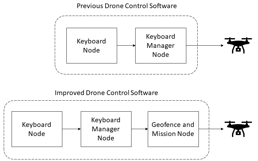
Improving the Drone Control Software
In Lab 2, we implemented a keyboard manager that published desired positions to be consumed by our drone. We now want to improve on that implementation by providing a couple of extra features:
- Tracking mission state: By tracking our mission state, we are able to process commands according to the specific mission state we are in.
- Geofencing: We want to enforce the drone only operates inside a predefined space for the safety of the drone and anyone using it.
To address these issues, we will explicitly define a new node as follows:
Create the “Geofence and Mission” Node
The first step in improving the drone’s control software will be to create the node. We will start the implementation of this node by only considering the first objective:
- Track the mission state of the drone
To start pull the latest code inside of a new Docker terminal.
# Change to lab directory
cd ~/CS4501-Labs/
# Clone the code
git pull
You should see a new workspace lab3_ws. This workspace will have the keyboard node and keyboard manager already implemented for you.
To track the drone’s mission state, we are going to need to create a new node in the simple_control package. Create a new node in the simple_control package in the lab3_ws workspace called geofence_and_mission.py, using what you have learned from Lab 1 and Lab 2.
Note: remember to give the node execution permissions using the chmod command.
The software of a robot operation can be complex. One way to manage this complexity is to decouple the functionality based on the system into discrete states and then organize the system as a Finite State Automaton (FSA). An FSA is a mathematical computation model that can be in exactly one of a finite number of states at any given time, and where the system can make well-defined transitions from one state to another in response to inputs or events.
Using an FSA we will design the geofence_and_mission.py node as follows
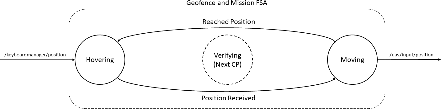
The geofence_and_mission.py node will consume a position that is published by the keyboard manager. If we are in state 1, the hovering state, and a new position is set then we will transition into state 3, the moving state. The moving state will move the quadrotor to the requested position. Once the drone reaches the required position, the FSA will transition back to state 1, the hovering state, and wait for the next input. There are 4 main design considerations to take into account:
- Keep track of the drone’s mission state.
- Encode state transitions.
- In lab 2, our keyboard manager integrated directly with the drone on the topic
/uav/input/position. We will now need the keyboard manager to publish positions instead (the desired input to the FSA). This allows us to separate the logic into different components as discussed previously. - Need a way to tell when quadrotor has reached the desired position so that it can transition from back to state 1.
To implement each of these points, we will do the following:
Fulfilling 1) We will implement a state machine. We can do that in many ways (e.g., nested switches, table mapping, state pattern), but for simplicity and given the number of states, we will use a sequence of nested predicates and start by declaring an enumeration that represents the possible states. An enumeration is a set of symbolic names (members) bound to unique, constant values.
Note: We are not yet using the VERIFYING state. This will be used later in the lab.
# A class to keep track of the quadrotors state
class DroneState(Enum):
  HOVERING = 1
  VERIFYING = 2
  MOVING = 3
Fulfilling 2) We will break the code up into a set of code functions. Each of the functions will encode the drone behavior within a state. We can then track the mission states using a class variable and call the correct function based on the state. For example, if the quadrotor is in the MOVING state, then the processMoving() function will be called.
# Check if the drone is in a moving state
if self.state == DroneState.MOVING:
  self.processMoving()
# If we are hovering then accept keyboard commands
elif self.state == DroneState.HOVERING:
  self.processHovering()
Fulfilling 3) We will subscribe to the /keyboardmanager/position topic using a subscriber so that we can start setting up the geofence_and_mission logic using this data. (Later in the lab we will adjust the keyboard manager so that it publishes the correct messages)
rospy.Subscriber('/keyboardmanager/position', Vector3, self.getKeyboardCommand, queue_size = 1)
Fulfilling 4) We will need a way to get the drone’s current position (we will do this after Checkpoint 1) to transition back from MOVING to HOVERING. Assuming we will have that information, we can implement a simple check to see how far away the quadrotor is from the desired goal. If the quadrotor is inside an acceptance-range, then the machine can transition back into a hovering state:
dx = self.goal_cmd.x - self.drone_position.x
dy = self.goal_cmd.y - self.drone_position.y
dz = self.goal_cmd.z - self.drone_position.z
# Euclidean distance
distance_to_goal = sqrt(pow(dx, 2) + pow(dy, 2) + pow(dz, 2))

# If goal is reached transition to hovering
if distance_to_goal < self.acceptance_range:
  self.state = DroneState.HOVERING
  ...
The Code for the Geofence and Mission node
Putting it all together: copy and paste the following code into the geofence_and_mission.py node. You will notice that we are using the previous points in the code and a few others that we discuss next.
#!/usr/bin/env python
import rospy
import time
import copy
from enum import Enum
from math import sqrt, pow
from geometry_msgs.msg import PoseStamped
from geometry_msgs.msg import Vector3
from geometry_msgs.msg import Point


# A class to keep track of the quadrotors state
class DroneState(Enum):
  HOVERING = 1
  VERIFYING = 2
  MOVING = 3


# Create a class which takes in a position and verifies it, keeps track of the state and publishes commands to a drone
class GeofenceAndMission:

  # Node initialization
  def __init__(self):

    # Create the publisher and subscriber
    self.position_pub = rospy.Publisher('/uav/input/position', Vector3, queue_size=1)
    self.keyboard_sub = rospy.Subscriber('/keyboardmanager/position', Vector3, self.getKeyboardCommand, queue_size = 1)

    # TO BE COMPLETED FOR CHECKPOINT 2
    # TODO: Add a position_sub that subscribes to the drones pose

    # TO BE COMPLETED FOR CHECKPOINT 3
    # TODO: Get the geofence parameters
    # Save the acceptance range
    self.acceptance_range = 0.5
    # Create the drones state as hovering
    self.state = DroneState.HOVERING
    rospy.loginfo(str(rospy.get_name()) + ": Current State: HOVERING")
    # Create the goal messages we are going to be sending
    self.goal_cmd = Vector3()

    # Create a point message that saves the drones current position
    self.drone_position = Point()

    # Start the drone a little bit off the ground
    self.goal_cmd.z = 3.0

    # Keeps track of whether the goal  position was changed or not
    self.goal_changed = False

    # Call the mainloop of our class
    self.mainloop()


  # Callback for the keyboard manager
  def getKeyboardCommand(self, msg):
    # Save the keyboard command
    if self.state == DroneState.HOVERING:
      self.goal_changed = True
      self.goal_cmd = copy.deepcopy(msg)


  # TO BE COMPLETED FOR CHECKPOINT 2
  # TODO: Add function to receive drone's position messages


  # Converts a position to string for printing
  def goalToString(self, msg):
    pos_str = "(" + str(msg.x)
    pos_str += ", " + str(msg.y)
    pos_str += ", " + str(msg.z) + ")"
    return pos_str


  # TO COMPLETE FOR CHECKPOINT 4
  # TODO: Implement processVerifying
  def processVerifying(self):
    # Check if the new goal is inside the geofence

    # If it is change state to moving
    # If it is not change to hovering
    pass


  # This function is called when we are in the hovering state
  def processHovering(self):
    # Print the requested goal if the position changed
    if self.goal_changed:
      rospy.loginfo(str(rospy.get_name()) + ": Requested Position: " + self.goalToString(self.goal_cmd))
      rospy.loginfo(str(rospy.get_name()) + ": Current State: MOVING")
      #  TO BE COMPLETED FOR CHECKPOINT 4
       # TODO: Update
      self.state = DroneState.MOVING
      self.goal_changed = False


  # This function is called when we are in the moving state
  def processMoving(self):
    # Compute the distance between requested position and current position
    dx = self.goal_cmd.x - self.drone_position.x
    dy = self.goal_cmd.y - self.drone_position.y
    dz = self.goal_cmd.z - self.drone_position.z

    # Euclidean distance
    distance_to_goal = sqrt(pow(dx, 2) + pow(dy, 2) + pow(dz, 2))
    # If goal is reached transition to hovering
    if distance_to_goal < self.acceptance_range:
      self.state = DroneState.HOVERING
      rospy.loginfo(str(rospy.get_name()) + ": Complete")
      rospy.loginfo(str(rospy.get_name()) + ": ----------------------------------")
      rospy.loginfo(str(rospy.get_name()) + ": Current State: HOVERING")


  # The main loop of the function
  def mainloop(self):
    # Set the rate of this loop
    rate = rospy.Rate(20)

    # While ROS is still running
    while not rospy.is_shutdown():
      # Publish the position
      self.position_pub.publish(self.goal_cmd)

      # Check if the drone is in a moving state
      if self.state == DroneState.MOVING:
        self.processMoving()
      # If we are hovering then accept keyboard commands
      elif self.state == DroneState.HOVERING:
        self.processHovering()
      elif self.state == DroneState.VERIFYING:
        self.processVerifying()

      # Sleep for the remainder of the loop
      rate.sleep()


if __name__ == '__main__':
  rospy.init_node('geofence_mission_node')
  try:
    ktp = GeofenceAndMission()
  except rospy.ROSInterruptException:
    pass
A useful resource to notice: ROS Logging
You will notice that this code no longer uses a standard print command.
Each of the print commands has been replaced with a rospy.loginfo(str(rospy.get_name()) + "...") command.
Using a log command in ROS is a good practice.
A print command will print a message to the terminal, with no extra logging information.
While using the terminal is easy enough for small, simple applications, there are many instances where this is impractical.
If there are lots of nodes, or a node that prints lots to the terminal, the messages you want to investigate will be difficult to find.
A rospy.loginfo() command will print a message to the terminal, as well as keep that message inside the ROS logs.
That way, you can go back and review your robot’s behavior at a later stage or easily compare logs with other people.
We also added the following string to each log: str(rospy.get_name()).
This is beneficial when there are multiple nodes printing messages to the terminal, as we will be able to differentiate messages from separate nodes more easily.
ROS logging allows you to create levels of messages so that important messages and less important messages can be distinguished.
The most important messages are called fatal messages. To publish a fatal message, you use the command rospy.logfatal().
The lowest level of a message is a debug message which can be logged using rospy.logdebug().
More on ROS logging can be found on the ROS Wiki.
Updating the Keyboard Manager
Now let’s make the changes to the keyboard_manager node to fulfill requirement #2. The keyboard_manager node needs to change in a few ways:
- We need to publich to the
/keyboardmanager/positiontopic which is of type Vector3 containing the setpoint command for the drone position. This topic is subscribed to by thegeofence_and_missionnode. - It should only publish a message once a position is set instead of continuously publishing any keyboard input. To do this, we will change the
keyboard_manageronly to publish messages when the user hits enter on their keyboard. - The
keyboard_managerwill display the position to be sent onto the terminal using logging.
To address each of these changes, we will make the following updates to the keyboard_manager.
Fulfilling 1) Change what the node publisher sends by updating the publishing statement:
self.position_pub = rospy.Publisher('/keyboardmanager/position', Vector3, queue_size=1)
Fulfilling 2) Change the main loop to only publish messages when the user hits enter:
# If the user presses the ENTER key
if self.key_code == Key.KEY_RETURN:
  # TO BE COMPLETED FOR CHECKPOINT 1
  # TODO : Publish the position (self.pos)
  rospy.loginfo(str(rospy.get_name()) + ": Sending Position")
Fulfilling 3) Log positions typed when they change. If the prev_pos and pos do not match, the pos has changed:
# TO BE COMPLETED FOR CHECKPOINT 1
# TODO: Check if the position has changed by comparing it to the current position
# Note you will need to change the if statement below from if False -> if #... TODO
if False:
  self.prev_pos = copy.deepcopy(self.pos)
  rospy.loginfo(str(rospy.get_name()) + ": Keyboard: " + self.goalToString(self.pos))
The Keyboard Manager Code
When you implement these changes your new keyboard_manager should look like this:
#!/usr/bin/env python
import rospy
import time
import copy
from keyboard.msg import Key
from geometry_msgs.msg import Vector3


# Create a class which we will use to take keyboard commands and convert them to a position
class KeyboardManager():
  # On node initialization
  def __init__(self):
    # Create the publisher and subscriber
    self.position_pub = rospy.Publisher('/keyboardmanager/position', Vector3, queue_size=1)
    self.keyboard_sub = rospy.Subscriber('/keyboard/keydown', Key, self.get_key, queue_size = 1)
    # Create the position message we are going to be sending
    self.pos = Vector3()
    self.prev_pos = Vector3()
    # Start the drone a little bit off the ground
    self.pos.z = 3.0
    # Create a variable we will use to hold the key code
    self.key_code = -1
    # Call the mainloop of our class
    self.mainloop()


  # Callback for the keyboard sub
  def get_key(self, msg):
    self.key_code = msg.code


  # Converts a position to string for printing
  def goalToString(self, msg):
    pos_str = "(" + str(msg.x)
    pos_str += ", " + str(msg.y)
    pos_str += ", " + str(msg.z) + ")"
    return pos_str


  def mainloop(self):
    # Set the rate of this loop
    rate = rospy.Rate(20)

    # While ROS is still running
    while not rospy.is_shutdown():

      # Left
      if self.key_code == Key.KEY_LEFT:
        self.pos.x += 1
      # Up
      if self.key_code == Key.KEY_UP:
        self.pos.y -= 1
      # Right
      if self.key_code == Key.KEY_RIGHT:
        self.pos.x -= 1
      # Down
      if self.key_code == Key.KEY_DOWN:
        self.pos.y += 1

      # TO BE COMPLETED FOR CHECKPOINT 1
      # TODO: Check if the position has changed by comparing it to the current position
      # Note you will need to change the if statement below from if False -> if #... TODO
      if False:
        self.prev_pos = copy.deepcopy(self.pos)
        rospy.loginfo(str(rospy.get_name()) + ": Keyboard: " + self.goalToString(self.pos))

      if self.key_code == Key.KEY_RETURN:
        # TO BE COMPLETED FOR CHECKPOINT 1
        # TODO : Publish the position (self.pos)
        rospy.loginfo(str(rospy.get_name()) + ": Sending Position")

      # Reset the code
      if self.key_code != -1:
        self.key_code = -1

      # Sleep for the remainder of the loop
      rate.sleep()


if __name__ == '__main__':
  rospy.init_node('keyboard_manager')
  try:
    ktp = KeyboardManager()
  except rospy.ROSInterruptException:
    pass
Putting it All Together
The last thing we need to do is to change our launch file so that we can run each of the nodes. To do that, add each node to the roslaunch file. The launch file is located in: ~/CS4501-Labs/lab3_ws/src/flightcontroller/launch/fly.launch
...
  <!--From Lab 2-->
  <node name="keyboard_manager_node" pkg="simple_control" type="keyboard_manager.py" output="screen"/>
  <node name="keyboard" pkg="keyboard" type="keyboard"/>
  <!-- To be added-->
 ...
Remember that you will need to catkin build and source devel.bash as discussed in Lab 2 before launching the program.
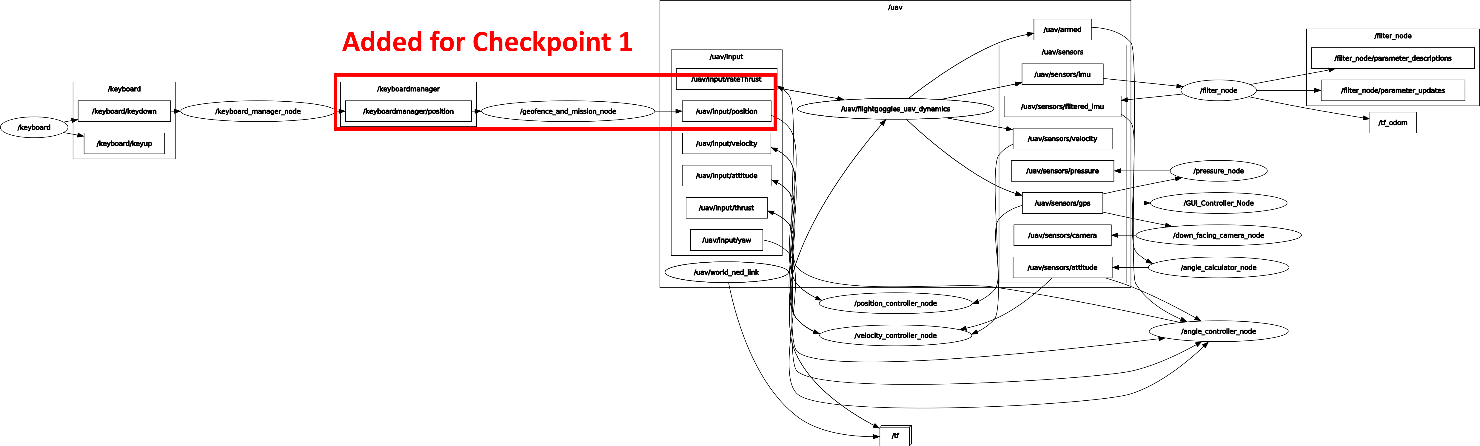
Checkpoint 1
Launch the simulator and check that you have correctly created the geofence and mission node as well as changed the keyboard manager to publish the correct data. Your ROS computation graph should look like the one below. Take a screenshot of the ROS computation graph:
Next, try to fly the quadrotor using the keyboard. Change the requested position using the keyboard keys. Once you have selected a position, hit the ENTER key to move the drone.
- What happens when you hit the enter key? Answer this in terms of the FSA states we implemented
- What happens when you request the drone to fly to a second position? Answer this in terms of the actual code used in
geofence_and_mission.py.
Message Types
Let’s implement the drone’s position tracking. Start by figuring out what topic the drone’s position is being published on. To do this, start the simulation and list the available topics:
rostopic list
Expected output
...
/uav/sensors/filtered_imu
/uav/sensors/gps
/uav/sensors/imu
...
The list of available topics should look as shown above. As you become more familiar with robotics in ROS, you will start to work with a set of common message types. This was purposefully done by the ROS developers to try and keep a set of standard messages and thus increase compatibility between different nodes, and allow for faster development.
One of the standard ROS message types is Pose. A pose represents a robot’s position and orientation. You will notice a topic called /uav/sensors/gps. Let’s identify what this topic is publishing and what message type it is. First, let’s see if this is the topic we want. Echo the topic:
rostopic echo /uav/sensors/gps
Expected output:
pose:
  position:
    x: -0.01205089835
    y: -0.014817305419
    z: 0.548691896515
  orientation:
    x: 0.000119791513234
    y: -8.21647300556e-05
    z: -0.000329261478202
    w: 0.999999935243
---
...
Nice! Just as we expected, there is a position and an orientation. Let’s now try and figure out what type this message is so that we can understand its structure and subscribe to it. To find more information about a topic, you can use another useful command: rostopic info. This command prints all the information for a given topic. Run the command:
rostopic info /uav/sensors/gps
Expected output:
Type: geometry_msgs/PoseStamped

Publishers:
 * /uav/flightgoggles_uav_dynamics (http://ros_docker:40897/)

Subscribers:
 * /GUI_Controller_Node (http://ros_docker:42357/)
 * /position_controller_node (http://ros_docker:46777/)
 * /down_facing_camera_node (http://ros_docker:40229/)
 * /pressure_node (http://ros_docker:37393/)
We can see that the message /uav/sensors/gps is of message type geometry_msgs/PoseStamped. To get more information about the specific message structure we can use another useful command rosmsg info. Run the command:
rosmsg info PoseStamped
Expected output:
[geometry_msgs/PoseStamped]:
std_msgs/Header header
  uint32 seq
  time stamp
  string frame_id
geometry_msgs/Pose pose
  geometry_msgs/Point position
    float64 x
    float64 y
    float64 z
  geometry_msgs/Quaternion orientation
    float64 x
    float64 y
    float64 z
    float64 w
More information about this message type (and others) can also be found on the ROS wiki
Using the output of the rosmsg info command for reference, we can see that it is a standard ROS message that consists of a header as well as a pose. Below is a diagram of the message:
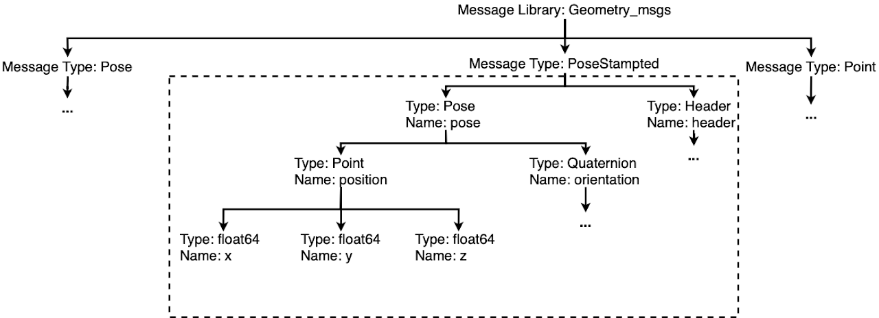
You will see that a Pose consists of a position and an orientation. Interestingly the position is of type Point, which is also declared in geometry_msgs. We find that the message type Point consists of three floats x, y, and, z. This method of identifying common messages can be repeated. In general, it is better to use standard ROS messages, as it allows faster development times and standardizes the messages sent on topics for easier integration between different projects. It is analogous to how cellphones all use standard communication standards (within a country at least). If every company designed their own, keeping track of which phone comm to use would be a nightmare.
Note: There are ways to create custom message types. You can find more information on this in the extra section. If possible, standard message usage is recommended.
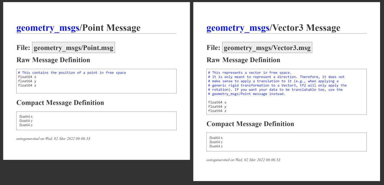
What’s in a message type?
Above we saw that the PoseStamped message type used the Point message type which consists of 3 fields x, y, z. However, if we look at the list of available message types, we see that there is also a Vector3 message type which has the same three fields x, y, z. The fields contained by these two message types are exactly the same! Why would we want to have two message types for the same information?
Looking at the comments in the documentation below, we can see why: they represent different things in the physical world.
Point represents a location in 3D, whereas Vector3 represents a direction.
The ROS developers understood these were two common use cases for x, y, z data, and so created different message types to represent them.
By using different message types to represent these different physical comments, it not only helps make your code more readable, maintainable, and portable, but also can allow for automatic type checking and let different libraries automatically know how to interpret the data.
The ROS library has many common types to represent many common physical quantities. In addition to trying to use an existing type when possible, you should always try to use a type that represents the physical quantity that you need to send.
Adding Position Tracking to Enable the Transition from Moving to Hovering
Using what we learned with message types, let’s adapt our geofence_and_mission.py node to subscribe to the Pose topic published by the simulator. Doing this will allow us to monitor when the drone reaches a goal and transitions from state MOVING back to state HOVERING. In the geofence_and_mission.py node, write code to fill in the two #TODO sections.
First, in the node initialization, subscribe to the drone’s pose using the correct topic name, and message type. Direct each of the messages to a callback.
Second, implement the callback for this message. The callback should store the drone’s position to the class variable self.drone_position. You can access each component of the message using standard dot notation. For instance, if I wanted to get the orientation of the quadrotor, I could use:
msg.pose.orientation
Where msg is passed into the callback as a function parameter.
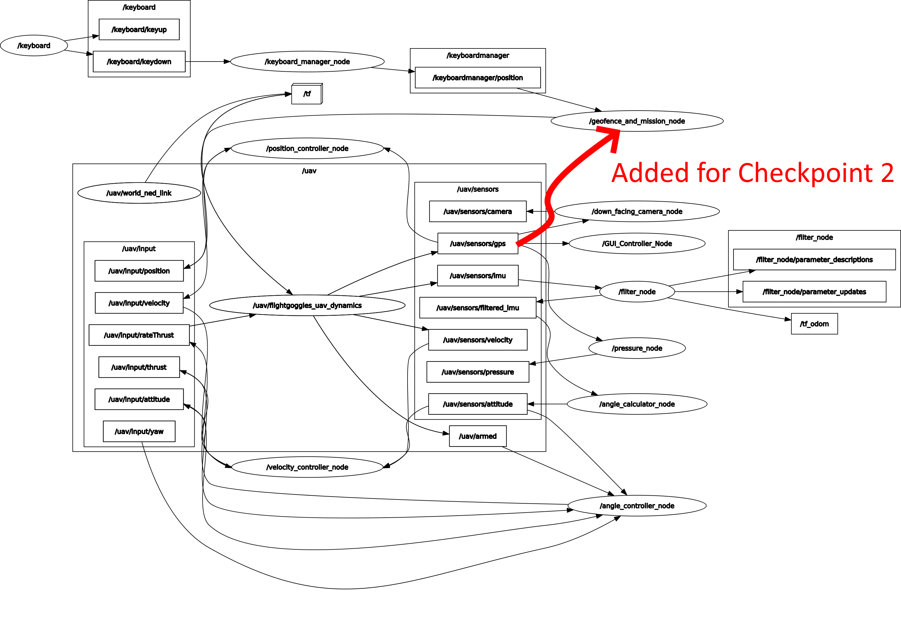
Checkpoint 2
Launch the simulator and check that you have correctly created the geofence and mission node as well as changed the keyboard manager to publish the correct data. Your ROS computation graph should look as shown below. Take a screenshot of the ROS computation graph:
Next, try to fly the quadrotor using the keyboard. You should see your quadrotor move after you hit the ENTER key.
- What happens when you request the drone to fly to a second position?
- Send a message to the drone while it is moving to a target position. What happens? Why?
Abstracting Parameters
Abstracting parameters from the code and placing them in a more accessible place is a common practice in software engineering. Without this, configuring codebases to a particular situation would be extremely labor-intensive. In terms of robotics, think about designing a package that can successfully navigate and control ground robots. In order to keep this package general and applicable to multiple ground vehicles, many parameters of the vehicle need to be abstracted, such as the maximum velocity, the maximum steering angle, the size, the sensor capabilities, etc. A good example of a package that is used in robotic navigation is move_base. This package is used in robots such as the PR2, Husky, and Turtlebot all shown below:
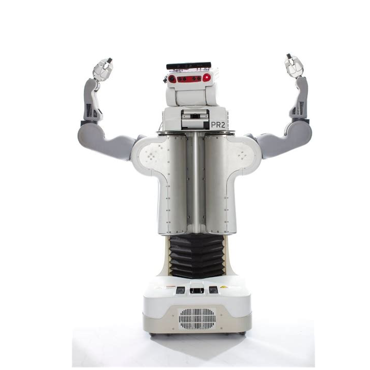
PR2 Robot
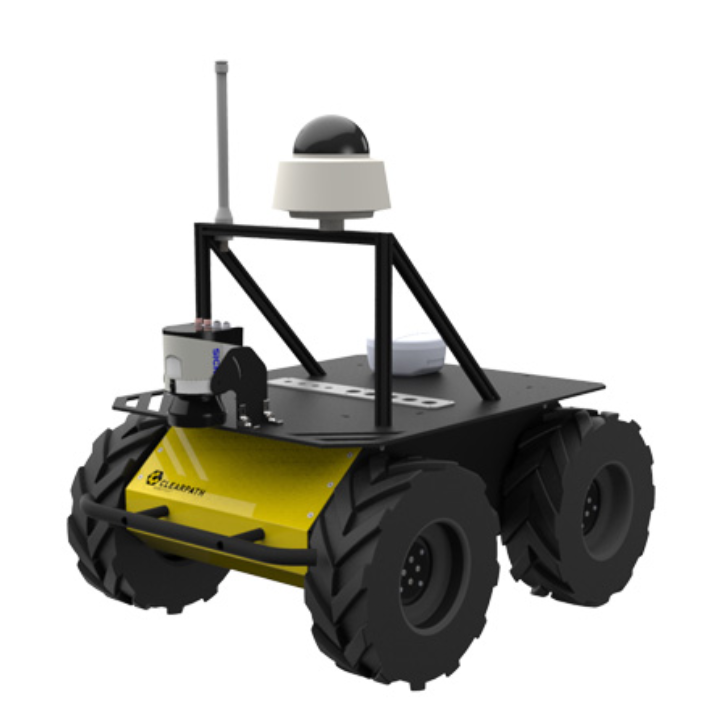
Husky Robot
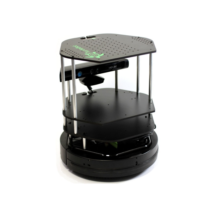
Turtlebot 2 Robot
Let’s learn how to configure our quadrotor to use a parameter server.
Adding a Verifying State
To learn to apply parameter servers, let’s start by implementing the verification state to forbid the quadrotor from flying outside of a virtual geofence. Verifying that a waypoint is within a geofence (a virtual cage) is a good practice as it makes sure that you do not accidentally send a waypoint to the quadrotor that causes it to fly away or crash into a known obstacle. In general, most commands sent to a robot that is going to result in the robot performing some action in the real-world should be verified for the safety of both the people around it and itself.
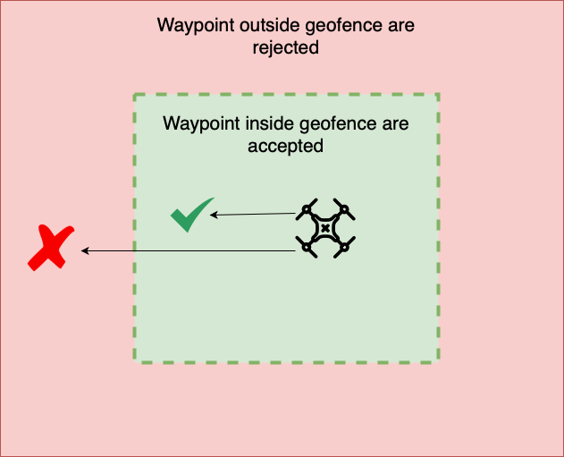
The first thing we need is to create a geofence area in such a way that it is easy for the user to change the parameters of the geofence. That way, if the drone is deployed into an area of a different size, it can quickly and easily change the geofence size without having to change the code.
Parameter Servers
We can do that using a parameter server. The ROS wiki describes the parameter server as “a shared, multi-variate dictionary that is accessible via network APIs. Nodes use this server to store and retrieve parameters at runtime”. In other words, our node can query this parameter server and get the geofence area dimensions. The benefit of doing this is we can move setting the parameters into the launch file. That way, if we want to change the geofence area size, all we have to do is change the values in the launch file. This is beneficial as any parameters you want to set get abstracted out of the code, making the code easier for you to manage. It also makes it easier for people using your code as they don’t need to understand your implementation to configure the parameters.
You could take this one step further and expose the parameters as command-line arguments, allowing you to pass the parameters in from the command line.
Extra: Here is more information on custom message types, and adding command-line arguments to a launch file
We will start by querying the parameter server for the geofence size and acceptance range from inside the verification node. We will call the verification node the geofence_and_mission_node. We will name the geofence area the geofence. Add the following code in the node initialization:
# Get the acceptance range
self.acceptance_range = rospy.get_param("/geofence_and_mission_node/acceptance_range", 0.5)

# Getting the geofence parameters
geofence_params = rospy.get_param('/geofence_and_mission_node/geofence', {'x': 5, 'y': 5, 'z': 5})
cx, cy, cz = geofence_params['x'], geofence_params['y'], geofence_params['z']

# Create the geofence

self.geofence_x = [-1 * cx, cx]
self.geofence_y = [-1 * cy, cy]
self.geofence_z = [0, cz]

# Display incoming parameters
rospy.loginfo(str(rospy.get_name()) + ": Launching with the following parameters:")
rospy.loginfo(str(rospy.get_name()) + ": Param: geofence x - " + str(self.geofence_x))
rospy.loginfo(str(rospy.get_name()) + ": Param: geofence y - " + str(self.geofence_y))
rospy.loginfo(str(rospy.get_name()) + ": Param: geofence z - " + str(self.geofence_z))
rospy.loginfo(str(rospy.get_name()) + ": Param: acceptance range - " + str(self.acceptance_range))
Let’s spend some time understanding how this code works.
First, we changed the acceptance range to be queried from the parameter server. We also give this parameter a default value of 0.5 (in case the parameter can not be found). Next, when we look at the geofence, we will notice that the default parameters are a dictionary of values. We abstract these dictionary values to cx, cy, and, cz. Recall that such values are set in the launch file. To set the parameters in the launch file (~/CS4501-Labs/lab3_ws/src/flightcontroller/launch/fly.launch) change it as follows:
<node name="geofence_and_mission_node" pkg="simple_control" type="geofence_and_mission.py" output="screen">
  <param name="geofence/x" type="double" value="5" />
  <param name="geofence/y" type="double" value="5" />
  <param name="geofence/z" type="double" value="2" />
  <param name="acceptance_range" type="double" value="0.5" />
</node>
You will notice that each of the parameters we query are now defined inside the launch file.
Checkpoint 3
Check that you can change the geofence parameters by changing the values in the launch file. Change the geofence size to {3, 3, 3}, and the acceptance range to 0.25. Run the simulator and show us your output:
Note: Do not change the default values inside the code; only change the launch file. This is advantageous in that we can adjust the behavior of the system without rebuilding, recoding, or redeploying the system.
Below is an example of what you would see when you launch the simulator after changing the launch file:

Verifying that Waypoints are within Cage
Next lets adapt our FSA to include a verifying state. This verification state will verify the command position and make sure it is inside the geofence before transitioning to a moving state. The design for the final geofence_and_mission node will be as follows:
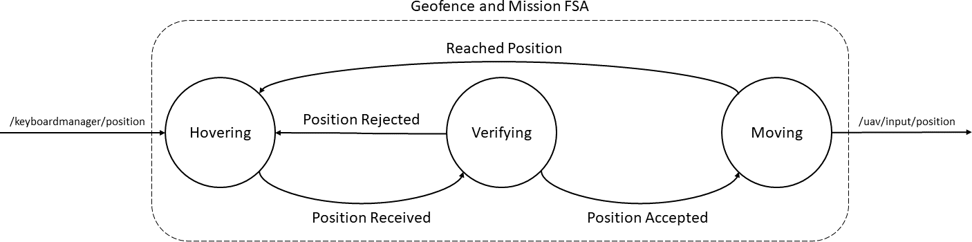
The new design uses an FSA, which works as follows: First when we receive a position message, we transition to a verifying state. The verifying state checks if the published position is inside the geofence. If the new position is outside the geofence, the position is rejected, and the FSA transitions back into the hovering state. If the position is inside the geofence, the position is accepted, and the FSA transitions to the moving state. When the drone reaches the final position, the FSA transitions back to the hovering state, where the next command can be given to the quadrotor.
Notice that inside the main loop you are constantly publishing the goal_cmd. You will thus need to make sure that you are not updating the goal_cmd until you are certain that it has been verified.
Update the geofence_and_mission.py node to implement the extended FSA.
Checkpoint 4
Show the quadrotor flying inside the geofence area. First, send the drone a waypoint inside the geofence area. Second, send the drone a waypoint outside of the geofence area.
Using ROS Services
For the last section of this lab we will implement two services that allow us to control our quadrotor’s behavior. Services, like topics, are another way to pass data between nodes in ROS. Services differ from topics in two key ways, 1) services are synchronous procedure calls, whereas topics are asynchronous communication busses, and 2) services return a response to each request, whereas topics do not. Each service will have a defined input and a defined output format. The node which advertises the service is called a server. The node which calls the service is called the client.
Services are generally used when you need to run functions that require a response. Good scenarios to use a service are:
- When you want to execute discrete actions on a robot, for instance
- Turning a sensor on or off
- Taking a picture with a camera
- When you want to execute computations on another node
Implementing a Service
The first service we will be implementing will allow us to “calibrate” the drone’s pressure sensor. A pressure sensor returns the atmospheric pressure, which at sea level is approximately 1,013.25 millibars. When invoked, the calibration service zeroes the baseline pressure so that later pressure differentials can be used to compute altitude estimates. The service will return the baseline pressure to the user.
Unlike topics that use a publish-subscribe architecture, services use a request-reply architecture. This interaction is defined by a pair of messages, one for the request and one for the reply. To declare this pair of messages, we need to build a service definition file. These service definition files are declared by us using ROS message types. Our service’s request will be a boolean value from the std_msgs library that describes whether the pressure sensor should be zeroed. Our service reply is a float value from the std_msgs library that contains the current baseline pressure reading.
Unlike topic messages, there are no class libraries for service types. This is because services are dynamic and build upon the existing ROS message types. Due to this, we need to 1) create the service definition file and 2) configure Catkin to build the service definition file. A similar process is done when you want to create custom message types used for topics.
Service definition files are typically put in a directory called srv.
- Start by creating the directory srv inside the
sensor_simulationpackage. - Inside the srv folder create the service definition file called
calibrate.srv
Now, let’s add content to the service definition file. Service definition files start with the specification of the request (input), followed by the specification of reply (output). The request and reply are separated using three dashes. Let’s add the request and reply for our pressure calibration service:
bool zero
---
float64 baseline
Remember, there are no standard class libraries for service types, and so rather than using a standard library as we do with messages, we need to configure our workspace to build them for us. To configure the workspace to build our new service files, we need to make changes to the makefiles. The service is being created inside the sensor_simulator package. Thus all changes to the Make files need to be done inside this package.
Update the sensor_simulation/CMakeList.txt file to include the message_generation package. message_generation will allow our package to generate the service message.
find_package(catkin REQUIRED COMPONENTS
  rospy
  std_msgs
  geometry_msgs
  sensor_msgs
  message_generation   # Add this line
)
We then need to add the additional package dependencies to the sensor_simulation/package.xml file. Add the following lines inside this file. These to allow our package to generate service messages.
<build_depend>message_generation</build_depend>
<build_export_depend>message_runtime</build_export_depend>
<exec_depend>message_runtime</exec_depend>
We then need to define which service message definition files we want to compile. Inside the sensor_simulation/CMakeList.txt package add our service definition file calibrate.srv:
add_service_files(
  FILES
  calibrate.srv
)
Finally, we need to update the message generation dependencies to include std_msgs as we are using a message from that library, namely bool and float64:
generate_messages(
  DEPENDENCIES
  std_msgs
)
Let’s now check if we have done everything correctly. It is always a good idea to break long processes like this into smaller steps to allow you to identify early on if you have made a mistake. Let’s compile the workspace and check if we can validate that the service call definition exists. To do this run:
cd ~/CS4501-Labs/lab3_ws/
catkin build
source devel/setup.bash
rossrv show calibrate.srv
The result should be:
[sensor_simulation/calibrate]:
bool zero
---
float64 baseline
If rossrv can find the service definition calibrate.srv you have configured your make files correctly, and catkin build can generate the message files. Catkin automatically generates three type definitions when we add a new service definition file. In general, if you create a service definition file <name>.srv, Catkin will create the following type definitions:
<name>Response<name>Request
Therefore in our case, there are three new types we can reference in Python, namely, calibrate, calibrateResponse, and calibrateRequest. A service that handles our calibration process will take in a calibrateRequest and return a calibrateResponse. Keeping this in the back of our minds, let’s move forward and implement the service handler inside the pressure node.
Start by importing the types created by Catkin. The pressure node is the server (receives the service request), and so we only need to import calibrate and the calibrateResponse. Add the following import to pressure.py:
from sensor_simulation.srv import calibrate, calibrateResponse
Next, let’s add the service to this node after the node initialization. This will advertise the service under the name calibrate_pressure. The service will have input and output as defined by the calibrate.srv and will redirect all service requests to the function self.calibrateFunction:
self.service = rospy.Service('calibrate_pressure', calibrate, self.calibrateFunction)
Finally, we can define the server function that will handle the service requests. You will notice that inside the pressure.py node, there is a class variable baseline_value that defaults to 0. This function will update that value:
# Saves the baseline value
def calibrateFunction(self, request):
  # If we want to calibrate
  if request.zero == True:
    self.baseline_value = self.pressure
  else:
    self.baseline_value = 0
  # Return the new baseline value
  return calibrateResponse(self.baseline_value)
Let’s again test if we have set the service up correctly. To test whether the service was set up correctly, launch the simulator. The first thing to check is that there are no errors when launching. If there are no errors, proceed to list the available services:
rosservice list
>>> /angle_calculator_node/get_loggers
>>> /angle_calculator_node/set_logger_level
>>> ...
You will notice that even for this small simulator, there are a lot of services. A quick way to find what you are looking for is to send all the output text to a grep command, known as piping to grep. grep is a linux program used for searching for keywords through text. Let’s try this now:
rosservice list | grep pressure
>>> /calibrate_pressure
>>> /pressure_sensor/get_loggers
>>> /pressure_sensor/set_logger_level
This command will output all services that contain the word pressure. Keep in mind that piping to grep is not specific to ROS and so can be used at any time in Linux. Now that we know that our service is being advertised let’s check the type of this service using:
rosservice info /calibrate_pressure
>>> Node: /pressure_sensor
>>> URI: rosrpc://ros_docker:43965
>>> Type: sensor_simulation/calibrate
>>> Args: zero
We can see that everything is as expected. We can see the Node which provides the service. We can see what message type the service uses and what the input arguments are. We are now ready to test our service. Open three terminals. In the first terminal, we will build and launch the simulator. In the second terminal, we will echo the pressure topic to see if our calibration was successful. In the third terminal, we will call the calibration service.
Terminal 1
source ~/CS4501-Labs/lab3_ws/devel/setup.bash
catkin build
roslaunch flightcontroller fly.launch
Terminal 2
source ~/CS4501-Labs/lab3_ws/devel/setup.bash
rostopic echo /uav/sensors/pressure
Expected output:
>>> data: 1013.24774066
>>> ---
>>> data: 1013.24769358
>>> ---
>>> data: 1013.24773901
>>> ...
Terminal 3
source ~/CS4501-Labs/lab3_ws/devel/setup.bash
rosservice call /calibrate_pressure 'True'
Expected output:
>>> baseline: 1013.24756649
If everything was implemented correctly after running the command in terminal 3, you should see that the topic /uav/sensors/pressure is now publishing messages that have been zeroed according to the returned baseline.
Terminal 2
>>> data: -0.00017854943485
>>> ---
>>> data: -0.000147954746467
>>> ---
>>> data: -0.00016459436074
Implementing your own service
Now use what you have learned to implement a service that will toggle the geofence area created during Checkpoint 2 on and off. Inside the geofence_and_mission node in the simple_control package, create a service toggle_geofence that has its inputs and outputs defined in the service definition file toggle_geofence.srv. This service should take in a boolean input parameter called geofence_on and output a boolean parameter success. The service should allow the user to turn the geofence area on or off and should return whether the call was a success or not (note: for our implementation it should always succeed in turning the geofence area on or off; however, we could imagine a different implementation that will not let you engage the geofence unless the quadrotor is already inside the geofence).
Checkpoint 5
Show that you can turn the geofence area on and off. First, set a waypoint outside the geofence area and attempt to fly to that position. The position should be rejected. Then turn the geofence area off using your service toggle_geofence. Resend the drone a position outside the geofence area. The drone should now fly to the waypoint.
Congratulations, you are done with Lab 3!
Final Check
- Show the computation graph for checkpoint 1
- Try to fly the drone using the keyboard
- What happens when you hit the enter key? Answer this in terms of the FSA states we implemented.
- What happens when you request the drone to fly to a second position? Answer this in terms of the actual code used in
geofence_and_mission.py.
- Try to fly the drone using the keyboard
- Show the computation graph for checkpoint 2
- Try to fly the drone using the keyboard
- What happens when you request the drone to fly to a second position?
- Send a message to the drone while it is moving to a target position. What happens? Why?
- Try to fly the drone using the keyboard
- Change the parameters in the launch file to
{3,3,3}and0.25- Show the output from running the simulation
- Fly the drone inside your geofence area. Your drone should:
- Fly to waypoints inside the geofence area using commands send via the keyboard.
- Reject waypoints that are outside the geofence area.
- You should be able to explain how you implemented the verification state.
- Turn the geofence area on or off using the
toggle_geofenceservice.- Show that after your geofence area is turned off, you can fly to a point outside the geofence area.