Side note: a problem with Euler angles is that the order in which rotations are applied can lead to different transformations. Thus the use of quaternions is generally preferred. Quaternions also provide many other benefits such as avoiding gimbal lock, which actually occurred during the Apollo missions. (Check out this video how a gimbal lock was narrowly avoided on the Apollo 13 mission.).
Why do we need transformations?
Robots employ many different coordinate systems (aka frames) to define their location, the location of their sensors and components, or the location of external entities. Transformations among those frames is necessary for the robot or a robot component to understand how to interpret data that is provided in a different frame. You may not have realized it, but we have already used many frames and implicit transformations in our previous labs. For example, we use the world frame when sensing the drone position, attitude, and velocity, to plan a path and implement the control commands to realize that path. Frames and transformations are everywhere, so let’s learn how to programmatically structure them in ROS.
Learning Objectives
At the end of this lab, you should understand:
- When and why we use transforms
- How to publish a transform in ROS
- How to use a ROS transform listener
- How to use a ROS transform to perform a coordinate transformation
- How to use a dynamic transform in ROS
Before Starting
Be sure to pull the latest code:
cd ~/CS4501-Labs
git pull
Scenario Overview
In previous labs, we specified the drone’s goal position using the command:
rostopic pub /uav/input/goal geometry_msgs/Vector3 '{x: -2, y: -1, z: 2.5}'
This command sends the drone to a position that we defined in our world frame. The drone navigated based on the assumption that it was operating in that world frame. Now, let’s see what would happen if that assumption does not hold.
For this lab, we will assume you have been hired by an online shopping company that has recently shown interest in delivering packages using drones. You are the lead engineer of the drone delivery system.
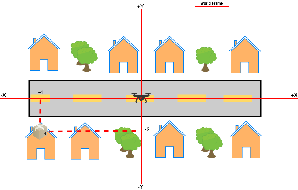
World Frame. In your first tests, you place the drone at the origin of the world frame (as illustrated in the figure above) and try to deliver packages to different houses. You start by delivering a package to the house on the bottom left of the figure (the one with the package). You find that all you need to do is send a Vector3 message to /uav/input/goal containing the coordinates [-4,-2].
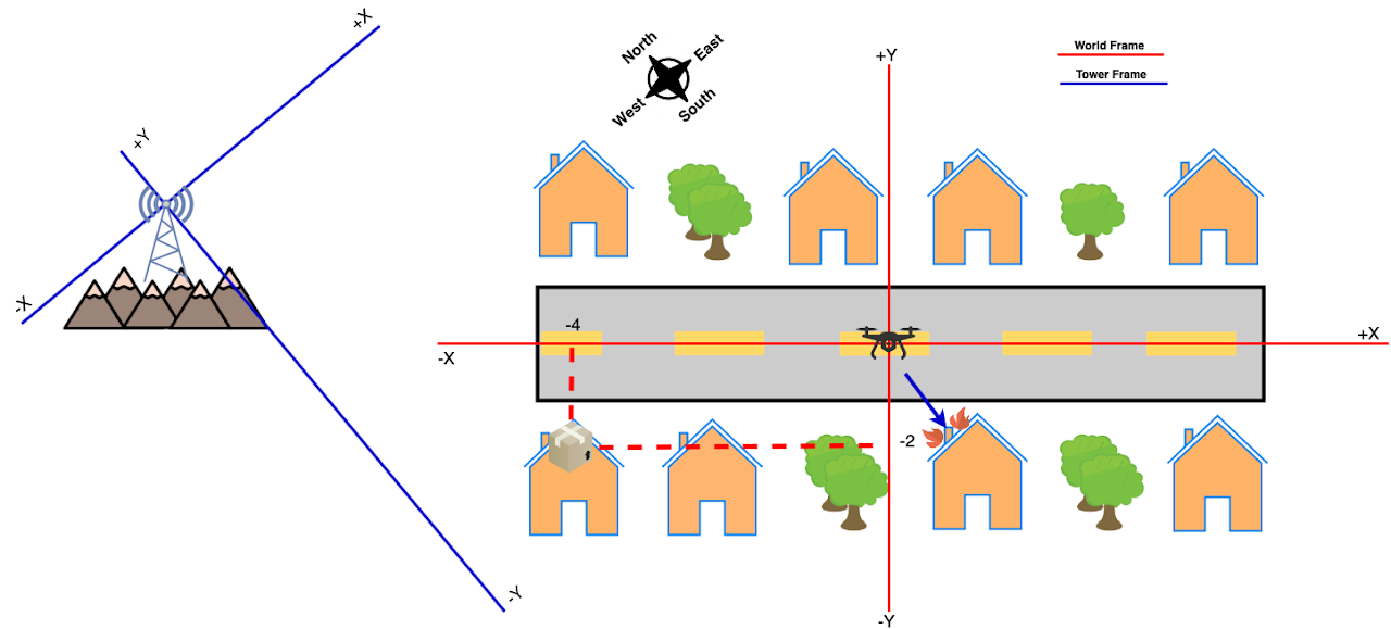
Tower Frame. As you expand your operation, you realize that you need a tower to control your family of drones. You place the tower at the top of a mountain to have longer communication reach. The tower, however, has a frame that is +Y aligned with the magnetic North. The tower then directs the drone to deliver a package to the location corresponding to the same house as before. You send the drone to that location when all of a sudden the drone flights to the right downwards and crashes into the house just below it. What happened? When the tower gave the drone the position to go to, it told the drone where to go in its own frame of reference. When you use poses that are not in the correct frame of reference, it can have unexpected and dangerous consequences.
In this lab, a tower node is provided. The tower will publish goal positions (once a drone’s path is complete) on the /tower/goal topic, using the tower frame. Your job will be to use ROS transforms to convert the tower’s commands into the world frame so that the drone can successfully navigate to the goals positions sent to the drone.
ROS Support for Frames and Transformations
ROS supports transformation between frames through the tf2 package, which provides very rich functionality, well beyond what is covered in this lab.
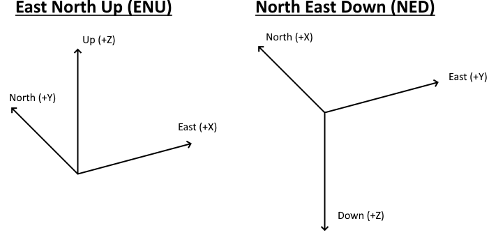
ROS also provides several standardized frames. For example, the ENU (East, North, Up) frame which is commonly used in ground robots has its positive x-axis pointing to the vehicle’s left, positive y pointing north, and the positive z axis pointing up. The frame we will be using in this lab is NED (North, East, Down), which is commonly used in aerial vehicles and has its x pointing north, positive y-axis pointing east, and positive z axis pointing down.
For the first part of this lab, we will be working with a particular kind of transform that does not change over time, known as a static transform. Our transform will aim to transform from the tower frame to the world frame. In contrast, a dynamic transform is one which changes as time goes by. For example, we would need a dynamic transform if our tower was attached to the delivery van; each time the van turned a corner the transform from the vans frame to the drone frame would also need to change. We will explore using a dynamic transform later in the lab.
Install tf2
In order to install the tf2 package, run the following command:
sudo apt-get install ros-melodic-tf2-tools ros-melodic-tf
Exploring the Coordinate Frames in our Simulator
Let’s start by exploring what frames are already available in our simulator. A quick way to do that is using the view_frames tool which will depict the system of coordinates used by a robot. Start two terminals and run the following commands:
Terminal 1:
source ~/CS4501-Labs/lab8_ws/devel/setup.bash
roslaunch flightcontroller fly.launch
Terminal 2:
source ~/CS4501-Labs/lab8_ws/devel/setup.bash
cd ~/CS4501-Labs/lab8_ws/
rosrun tf2_tools view_frames.py
The view_frames.py script provided from tf2_tools produces a PDF giving information about the current transformations available. In the ~/CS4501-Labs/lab8_ws/ directory you should have a file frames.pdf with a content similar to the image below:
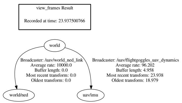
The picture above shows us that we have a small tree of transforms, rooted in the frame world with two child frames. Note that in ROS, each frame has a unique string identifier.
The first child frame is the world/ned frame which is being used by the drone dynamics. As discussed above, drones often use a NED coordinate system, and thus this transform is taking the world frame, which is in ENU, and converting it to NED so that the drone can use it to fly. This system of coordinates is always fixed.
The second child frame is uav/imu which corresponds to the body frame of the drone with its origin at the center of the robot. Thus, the body frame moves with the drone and it is valid only for a small time interval. For example, if we were to use the drone’s camera to determine the location of the an object relative to the drone, the camera would operate in the uav/imu frame.
The important part to notice is that ROS provides a way to define frames, to access them, and to relate them (the labels associated with each edge will be explained as we introduce more functionality of the tf2 package.)
Defining a transformation in ROS
To support transformations of geometric data, ROS provides the message class geometry_msgs/TransformStamped:
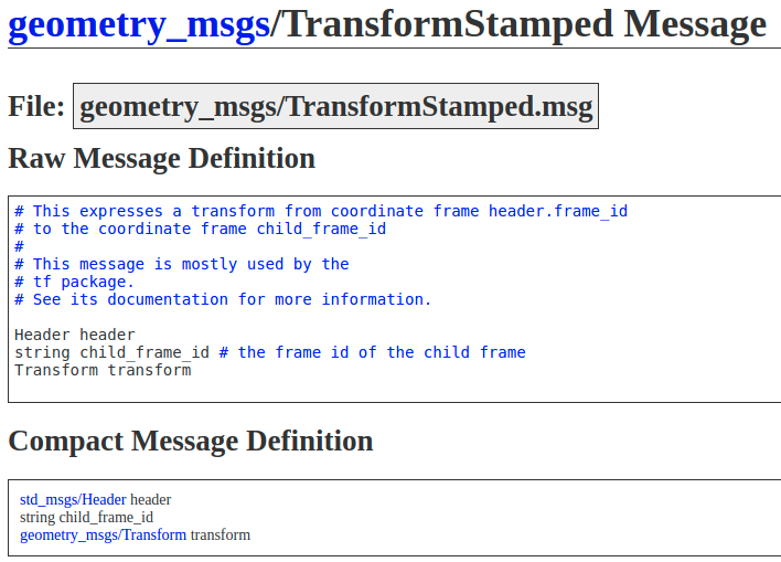
Using this message, a transformation is a function that transforms coordinates from the frame specified in header.frame_id to the coordinates specified in the child_frame_id.
Going back to our tree of frames in the view_frames output, the left-edge has header.frame_id set to 'world', and child_frame_id to 'world/ned'.
The transform attribute is defined as a message of type geometry_msgs/Transform, which consists of the mathematical transformation between two 3D Cartesian frames translation followed by a rotation.
The translation component is similar to a transformation in geometry and adds translation.x, translation.y and translation.z to the parents frames x, y and z coordinates.
A rotation can be specified either using Euler angles (roll, pitch, and yaw) or a quaternion (a vector in x,y,z, and a rotation w).
Defining our own Transformation
In this lab, we are aiming to transform the tower reported positions into the corresponding positions in the world frame that our drone understands. The diagram below gives specifics about the location of the tower relative to the origin of our world.
Important: tf2 can transform coordinates in both directions across an edge or a sequence of edges in the transform tree. Here, we will calculate the transform from the world frame to the tower frame. Then, later on we will ask tf2 to translate points from the tower frame into the world frame. It will internally calculate the inverse transform for us and perform the transformation.
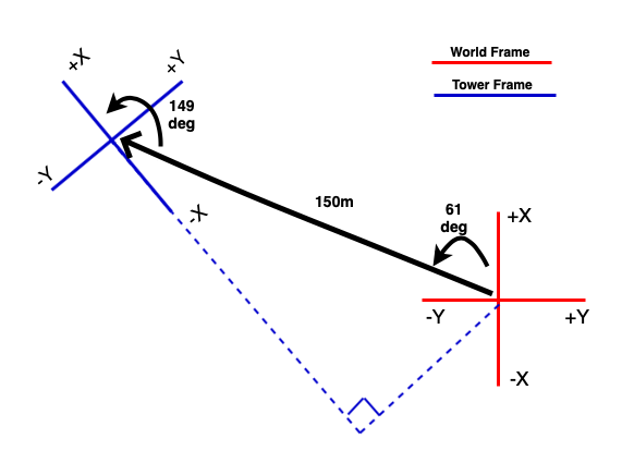
Now, using trigonometry (Transformation lecture – just for 2D in this case because we are ignoring altitude), develop the transformation function to do just that.
Remember that the transform, similar to a geometry_msgs/Transform message, must include a translation and a rotation. Use Euler angles for the rotation. Since we are using the NED convention (x points north, y points east, and z points down), the rotation matrix must be adjusted to:
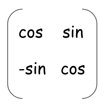
A positive yaw angle is one that moves from the +X axis to the +Y axis. In the case of NED frames this means that positive is clockwise.
Self-Checkpoint
To test that you have derived the correct transformation, manually transform these inputs using your formulas and check that you get the following output. Do not move on with the lab until your transformation is correct.
- World [0.0, 10.0] -> Tower [-133.6, 85.9]
- World [10.0, 10.0] -> Tower [-124.9, 90.9]
- World [-10.0, 10.0] -> Tower [-142.2, 80.9]
- World [10.0, -10.0] -> Tower [-114.9, 73.6]
- World [-100.0, 100.0] -> Tower [-265.2, 113.9]
- World [-120.0, 80.0] -> Tower [-272.5, 86.5]
- World [-200.0, 100.0] -> Tower [-351.8, 63.9]
Note: These answers have been rounded to the first decimal.
Broadcasting a Transformation
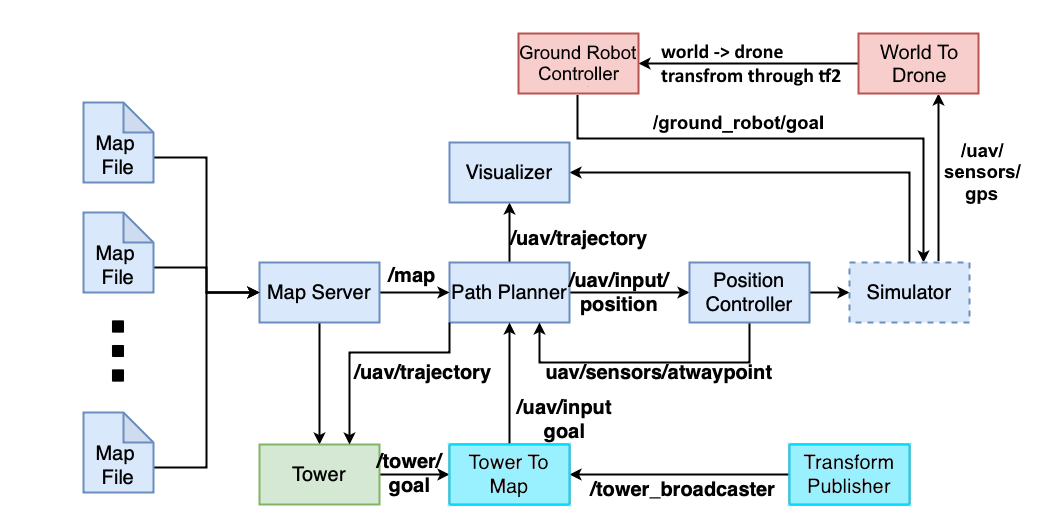
Let’s now use that transformation as part of our system. The architecture of the system we will develop for Checkpoint #1 is shown below. The blue nodes are similar to those in Lab 7. The green node is the new Tower node that is given to you, and the red nodes are what we will need to implement.
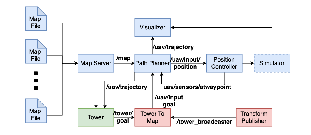
The package tf2 provides a broadcasting mechanism through which it sets an internal node to send out time stamped transformations to anyone that is listening. The idea is that all components of the system can access and use the transforms provided by other components, and continually broadcasting them makes sense if they are likely to change over time or if they are consumed at different times.
A node that needs to retrieve transformations from the system creates a transform listener. When the node needs to apply a transformation from frame A to frame B, it uses the listener to obtain that transform from the system and then applies it. Observe that a transform listener can be used to retrieve multiple transforms, while a typical ROS subscriber may only receive messages on one topic.
Broadcasting setup. As mentioned earlier, in this lab we will initially use a static broadcaster since the transformation from tower frame to world frame is time-independent. Broadcasting static transforms is so common, that tf2 provides a built-in static_transform_publisher node that we can add directly to our fly.launch file.
<node pkg="tf2_ros" type="static_transform_publisher" name="tower_broadcaster" args="TODO"/>
static_transform_publisher takes as arguments the three components of the translation, the three angles of rotation, the parent frame id, and the child frame id as follows.
x y z yaw pitch roll frame_id child_frame_id
Our job now is to replace the TODO in the arguments in the launch file line above with your computed transform. You must have the frame_id be the world frame and the chile_frame_id be the tower frame
A few things to keep in mind:
- In our context: z, pitch, and roll should be set to zero since we are operating in just 2D.
static_transform_publisheronly requires the rotation angle between the frames over x and y (rotation between x and y is the yaw) from which it computes the necessary trigonometry for us. The rotation angle must be specified in radians (not degrees) and again since our frames are in NED, clockwise is considered a positive rotation.- We are converting from the
towerframe to theworldframe - Precision is important. While above we rounded to 2 decimal places, consider using full decimal places in the launch file. 2 decimal places is not sufficient.
Once you are done, ROS offers capabilities to inspect the values sent through the system. To view the transformation you just defined, use the following command after you start the simulator and confirm that the translation and rotation match what you expect from your calculations above:
rosrun tf tf_echo world tower
>>> Translation: [..., ..., ...]
>>> Rotation: in Quaternion [..., ..., ..., ...]
            in RPY (radian) [..., ..., ...]
            in RPY (degree) [..., ..., ...]
Now, when we use it in our system, we will ask for the transformation in the other direction. To view this, run:
rosrun tf tf_echo tower world
>>> Translation: [..., ..., ...]
>>> Rotation: in Quaternion [..., ..., ..., ...]
            in RPY (radian) [..., ..., ...]
            in RPY (degree) [..., ..., ...]
Checkpoint 0
- How do the transforms in the different directions relate?
Listening and Transforming
Using static_transform_publisher we just set up a node to broadcast the transform from the tower frame to the world frame. Our drone needs to listen for this transform so that it can transform the goals that it receives in the tower frame to the world frame.
Listening Setup
To listen to the broadcasted transforms, we use a TransformListener. This can be created as follows:
self.tfBuffer = tf2_ros.Buffer()
self.listener = tf2_ros.TransformListener(self.tfBuffer)
Since nodes in ROS run in their own process and their execution order is not enforced, it is possible that the transformation you need is not available when requested, so it is a good practice to enclose the lookup call for the transform in a try block as follows. We will use the code below in our main loop to always pull the most recent transform. Although this is a static transform and thus we do not expect it to change, asking for the transform every time through the loop allows us to not have to wait for the static transform to become available, and also re-use the same code constructs when we employ dynamic transforms.
try:
  # lookup_transform arguments are target_frame, source_frame, and time
  transform = self.tfBuffer.lookup_transform('world', 'tower', rospy.Time())
except (tf2_ros.LookupException, tf2_ros.ConnectivityException, tf2_ros.ExtrapolationException):
  continue
Applying the Transform
The above code gave us the variable transform. One of the functions provided from tf2 allows us to apply transforms directly to Geometry PointStamped messages to move across frames as shown below:
from tf2_geometry_msgs import do_transform_point
#...
new_point = do_transform_point(point, transform)
Where point is point in coordinates you want to transform, and transform is the transform we just looked up and intend to apply to that point.
Using the Goals set by the Tower Frame in the Drone Planner
Let’s create a node tower_to_map.py that subscribes to /tower/goal (which is in the tower frame) and publishes a goal for our drone on the topic /uav/input/goal (in the world frame). The tower waits for about 10 seconds before it broadcasts the first goal. The node will use the transform declared by the static_transform_publisher to transform the goal across the frames. To do this, complete the following steps:
Step 1: Create the file tower_to_map.py in the simple_control package with the skeleton code given below. Remember to make the file executable.
Step 2: Add the node to fly.launch.
Step 3: Implement the TODOs in the following code using what we just learned about trasnforms.
#!/usr/bin/env python
import rospy
import tf2_ros
import time
import copy
from geometry_msgs.msg import Vector3
from geometry_msgs.msg import PointStamped
from tf2_geometry_msgs import do_transform_point

class TowerToMap:

  def __init__(self):
    time.sleep(10)
    # Used by the callback for the topic /tower/goal
    self.goal = None
    # TODO: Instantiate the Buffer and TransformListener

    # TODO: Goal publisher on topic /uav/input/goal

    # TODO: Tower goal subscriber to topic /tower/goal


    # start main loop
    self.mainloop()

  #TODO: Callback for the tower goal subscriber

  def mainloop(self):
    # Set the rate of this loop
    rate = rospy.Rate(2)
    while not rospy.is_shutdown():
      if self.goal:

        try:
          #TODO: Lookup the tower to world transform

          #TODO: Convert the goal to a PointStamped

          #TODO: Use the do_transform_point function to convert the point using the transform

          #TODO: Convert the point back into a vector message containing integers

          #TODO: Publish the vector
          rospy.loginfo(str(rospy.get_name()) + ": Publishing Transformed Goal {}".format([msg.x, msg.y]))

          # The tower will automatically send you a new goal once the drone reaches the requested position.
          #TODO: Reset the goal

        except (tf2_ros.LookupException, tf2_ros.ConnectivityException, tf2_ros.ExtrapolationException):
          print('tf2 exception, continuing')
          continue

      rate.sleep()

if __name__ == '__main__':
  rospy.init_node('tower_to_map')
  try:
    tom = TowerToMap()
  except rospy.ROSInterruptException:
    pass
After you have implemented this node, the tower node will publish a new goal after your drone has reached its current goal. Thus, your drone should now successfully navigate the map getting new goals each time it reaches its current goal.
Checkpoint 1
- Explain how you calculated the values for
argsfor thetower_broadcasternode - Run the simulator and show that your drone is capable of reaching 3 different goals sent by the tower.
Dynamic Transforms
In the previous checkpoint, the transform was static and did not change during the execution. That is useful for when we need to transform between two frames that are not moving, in this case the tower and the world. We will now explore what happens when we need to transform between a moving object and a stationary object.
Our drone is flying around the world at a height of 9m. We want to add a ground robot whose job is to follow the drone from the ground and provide support by giving the drone a place to land, recharge, and pick up its next package for delivery. However, due to limitations on its sensors, the ground robot cannot receive the signals from the tower. Instead, it relies on the drone for its goal information. Because the ground robot wants to be available to the drone (in case it needs to land), it always tries to center itself under the drone. This means that, in the drone’s coordinate frame, the ground robot always wants to be at (0,0). However, the ground robot takes its commands in the world frame. Thus, we will need to use a dynamic transform to translate between the two.
The drone publishes a dynamic transform from its coordinate frame to the world coordinate frame. The ground robot can use this transform to transform to sets its (0,0) position in the drone frame into the world frame.
Note that the drone to world transform occurs in three dimensions, but our ground robot can only move in two dimensions. As shown in the figure below, the transform between the drone and world frame has a z component. Because our ground robot cannot move in the z dimension, we can ask for the transform to (0,0,0), and ignore the z component.
Side note: you may have noticed that, since we have access to all the data of all robots through our simulator, it would be possible for the ground robot to just listen to the /uav/sensors/gps topic and simply follow the drone since the GPS reports position in the world frame. In practice, however, not all data is shared among robots (i.e., the
commands sent to the drone may not be accessible to the ground robot) and when they are shared they come in the wrong format. So this section of the lab help us to get accustomed to using the transform framework for the benefits it provides over this approach.
We will now extend our system with two nodes. The nodes implemented earlier for handling the static transform are colored teal. The nodes we will be implementing for the dynamic transform are colored red.
Setting up the dynamic transformation
When we used tfBuffer.lookup_transform('world', 'tower', rospy.Time()) with the static transform, the last argument, rospy.Time(), did not matter - the transformation would always be the same. However, with dynamic transformations, the transform time is very important. Using rospy.Time() asks tf2 for the most recent transform. Internally tf2 maintains a lookup that uses the parent frame, child frame, and time as keys to retrieve the required transform.
For the static transform, we used a built-in node that tf2 provided and set everything up in the launch file. To transition to a dynamic transform, we will need to create our own node that regularly calculates the current transformation and broadcasts this to the rest of the system. We will build a node that broadcasts the transform from drone to world as time progresses. To do this, we will use a TransformBroadcaster. The broadcaster uses the TransformStamped message type which we saw earlier. Let us review it again since we will not be directly using it in our code:
This message includes the Transform we saw earlier, and it also includes information on the parent frame (header.frame_id), the child frame (child_frame_id), and the time (header.stamp). These fields together tell the system what two frames this transform links together and when it was generated. In order to use this type, you will need to fill in all of these fields, along with the transform itself.
 br = tf2_ros.TransformBroadcaster()
 transform = TransformStamped()
 # fill in parent frame, child frame, timestamp, and transform fields
 br.sendTransform(transform)
You will need to create a node world_to_drone.py that uses the /uav/sensors/gps topic, which gives us the drone’s position in the world frame, to produce the transformation from the world frame to the drone frame:
Step 1: Create the file world_to_drone.py in the simple_control package with the skeleton code given below. Remember to make the file executable.
Step 2: Add the node to fly.launch.
Step 3: Implement the TODOs in the following code using what we have just learned about dynamic transformations.
#!/usr/bin/env python
import rospy
import tf2_ros
import time
import copy
import math
from geometry_msgs.msg import Vector3
from tf.transformations import quaternion_from_euler, euler_from_quaternion
from geometry_msgs.msg import PointStamped, PoseStamped, TransformStamped
from tf2_geometry_msgs import do_transform_point


class WorldToDrone:

    def __init__(self):
        time.sleep(10)
        # Used by the callback for the topic /tower/goal
        self.gps = None
        self.transform_stamped = TransformStamped()
        # TODO: Instantiate the Broadcaster

        # TODO: Drone GPS subscriber to topic /uav/sensors/gps

        # TODO: fill in the parent and child frames
        self.transform_stamped.header.frame_id = 'TODO'
        self.transform_stamped.child_frame_id = 'TODO'

        # start main loop
        self.mainloop()

    # TODO: Callback for the GPS

    def mainloop(self):
        # Set the rate of this loop
        rate = rospy.Rate(2)
        while not rospy.is_shutdown():
            if self.gps:
                # TODO: Use the GPS position to set up the transform
                self.transform_stamped.transform.translation = None  # TODO: set the Translation from the GPS
                self.transform_stamped.transform.rotation = None  # TODO: set the quaternion from the GPS

                # TODO: Update the header to the current timestamp
                self.transform_stamped.header.stamp = 0  # TODO: set to the current time
                # TODO: Broadcast the transform

            rate.sleep()


if __name__ == '__main__':
    rospy.init_node('world_to_drone')
    try:
        wod = WorldToDrone()
    except rospy.ROSInterruptException:
        pass
Now let’s link the Drone frame to the Ground Robot
Let’s now create a node ground_robot_controller.py that publishes a goal to our ground robot on the topic /ground_robot/goal (in the world frame). The node will use the transform published by the drone to transform the goal across the frames. To do this complete the following steps:
Step 1: Create the file ground_robot_controller.py in the simple_control package with the skeleton code given below. Remember to make the file executable.
Step 2: Add the node to fly.launch.
Step 3: Implement the TODOs in the following code.
Note: The robot may not follow the drone exactly and may seem noisy in its movements as shown below. This is expected and will be addressed in checkpoint 3.
#!/usr/bin/env python
import rospy
import tf2_ros
import time
import copy
from geometry_msgs.msg import Vector3
from geometry_msgs.msg import PointStamped
from tf2_geometry_msgs import do_transform_point


class GroundRobotController:

    def __init__(self):
        time.sleep(20)  # takes longer for the other items to come up
        # Our goal is 0,0,0 *in the drone frame*
        self.goal = Vector3()
        # TODO: Instantiate the Buffer and TransformListener

        # TODO: set up publisher to /ground_robot/goal - this will publish *in the world frame*

        # start main loop
        self.mainloop()


    def mainloop(self):
        # Set the rate of this loop
        rate = rospy.Rate(2)
        while not rospy.is_shutdown():
            if self.goal:

                try:
                    # TODO: Lookup the drone to world transform

                    # TODO: Convert the goal to a PointStamped

                    # TODO: Use the do_transform_point function to convert the point using the transform

                    # TODO: Convert the point back into a vector message containing integers

                    # TODO: Publish the vector
                    rospy.loginfo(str(rospy.get_name()) + ": Publishing Transformed Goal {}".format([msg.x, msg.y]))

                except (tf2_ros.LookupException, tf2_ros.ConnectivityException, tf2_ros.ExtrapolationException):
                    continue

            rate.sleep()


if __name__ == '__main__':
    rospy.init_node('ground_robot_controller')
    try:
        tom = GroundRobotController()
    except rospy.ROSInterruptException:
        pass
Checkpoint 2
- Explain how you implemented the transformation broadcaster logic
- Explain how you implemented the ground robot controller
- Show that the robot can follow your drone to 3 waypoints sent by the tower
Fixing the Wobbling Frame
In the previous checkpoint we observed that the ground robot wobbled underneath of the drone as it flew and it was not very effective at following the drone directly. Let’s examine why this happened. Because we are using the GPS position and orientation directly, the drone frame has the same position and orientation as the drone. This means that the point (0,0,0) for the drone is at a height of roughly 9m in the world frame. Further, as the drone pitches and rolls during navigation, the drone frame also pitches and rolls with respect to the world frame.
Since we want the ground robot to be directly below the drone regardless of its pitch and roll, we need to account for this in our transformation.
We want the frame to be parallel with the ground, which means having the pitch and roll stay constant at 0. To do this, we will take the orientation given by the GPS and zero out the roll and pitch components before adding it to the world to drone transform. The orientation that we receive from the GPS is given as a quaternion, which makes it difficult for us to directly reason about the roll, pitch, and yaw. Luckily, utility functions are provided that can switch between them. You will see we have already imported the quaternion_to_euler and euler_to_quaternion functions.
Step 1: Convert the GPS quaternion into roll, pitch, and yaw:
roll, pitch, yaw = euler_from_quaternion((orientation.x, orientation.y, orientation.z, orientation.w))
Step 2: Create a new quaternion, only preserving the yaw portion:
x,y,z,w = quaternion_from_euler(0, 0, yaw)
Step 3: Use the values to set the quaternion we are giving to the broadcaster.
You should now be able to re-run the simulator and observe that the ground robot follows the drone more closely and with less noise.
Checkpoint 3
- Show how your ground robot more closely follows the drone.
Congratulations, you are done with lab 8!
Final Check
-
How do the transforms in the different directions relate?
- Verify that your drone can visit the points given by the tower
- Explain how you calculated the values for
argsfor transform - Run the simulator and show that your drone is capable of reaching 3 different goals sent by the tower.
- Explain how you calculated the values for
- Verify that the ground robot can follow your drone
- Explain how you implemented the transformation broadcaster logic
- Explain how you implemented the ground robot controller
- Show that the robot can follow your drone to 3 waypoints sent by the tower
- Verify that the ground robot more closely follows the drone