At the end of the test you might get an error which states: ROSException: publish() to a closed topic. This is normal and might occur depending on the order nodes where shutdown by rostest. It should not affect the success or failure of your tests.
PID Controllers and Rostest
A PID Controller is an algorithm that uses the error between a setpoint and a measurement to adjust the system’s output with the goal of maintaining the set point. A PID relies on three terms (P,I,D) to control the system output to minimize the error. PIDs’ broad applicability and popularity in robotics makes them worth their own lab.
Learning Objectives
In this lab, we will implement and test a PID controller. At the end of this lab, you should be able to:
- Implement a PID following system-level requirements
- Understand the role of each term in a PID and how to set them
- Use the ROS testing framework rostest to implement system tests
Overall Scenario for the Lab
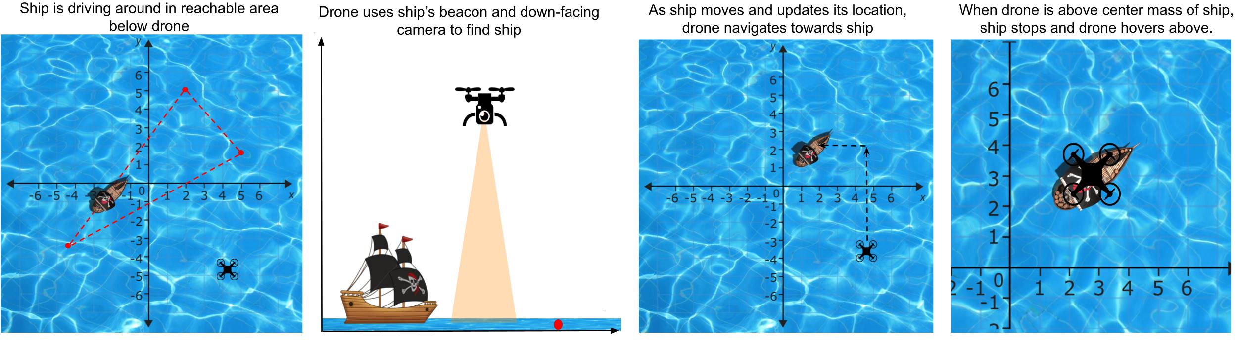
In this lab, we will be developing a drone subsystem, ship_follower_node, that attempts to position the drone on top of a moving ship at sea.
The drone will first head towards a ship’s rough location using the ship’s beacon. Then, when the ship is within the sights of the drone’s down-facing camera, it will adjust its position using its PID controller to be centered on top of the ship.
Lab Requirements
Retrieve the new code base for Lab 6 by running:
$ cd ~/Desktop/CS4501-Labs
$ git pull
Requirements for Ship Follower - ship_follower_node
As mentioned earlier, the goal of ship_follower_node is to position your drone over a ship.
The positioning requires two steps:
- Take the drone close to the ship using the
/ship/beacon - Use your well-tuned PID controllers (one for the x and for the y axis) to position the drone on top of the ship based on the ship pose estimates in
/ship_image_locationcomputed from the down-facing camera images.
Once the node is implemented and the PID fully tuned, the drone should be able to:
- Follow the ship without losing sight of it
- Achieve and maintain a distance within the
ship_epsilonupon stabilizing
The drone must fly at 9m of altitude for its perception capabilities to work correctly. At that altitude the viewfinder for the camera will show about 1 unit square. The camera images are 200 pixels by 200 pixels.
The node must publish to the topic /uav/input/position_request at a rate that can keep up with the ship’s speed.
As in previous labs, /uav/input/position_request supplies state_safety_node with x, y, z coordinates to which the drone will attempt to fly.
Inputs required:
The ship_follower_node node should subscribe to:
/uav/sensors/gps, which contains the x,y,z values for the position of the drone/ship/beacon, which gives a coarse estimate of the relative location of the ship/ship_image_location, which is published by theperception_nodeand supplies an estimated pose of the ship in the image captured by thedownward_facing_cameranode of the drone; the PID controller will work based on the measures captured by this estimate/ship_detected, which determines whether the ship is in the viewfinder/ship/stop_notification, which indicates whether the ship has stopped.
Configuration parameters required:
The node must read the following parameters from the parameter server for the x and y PIDs: the proportional constants px and py, the integral constants ix and iy, and the derivative constants dx and dy. Those parameters must be part of the relevant launch file.
The Ship Node - ship_node
Since the ship_follower_node gets a lot of information from ship_node and we will be using ship_node to test ship_follower_node, it is worth understanding some of its operations.
This node is configurable via two parameters: ship_velocity and ship_waypoints.
ship_waypoints determines the waypoints that the ship visits as it navigates around the x,y plane. Once it reaches the end of the series of waypoints, it returns to the first waypoint. If it is given a single waypoint, it idles at that waypoint. ship_velocity sets the velocity with which the ship travels between waypoints, in units per second. For testing, it has been constrained to values between 0.0 and 1.0.
The acceptable tolerance with which the drone is determined to be on top of the ship is configured inside fly.launch using ship_epsilon. Although you can modify it to understand its effect, by the end of the PID’s implementation and for the checkpoints, that epsilon must be at least 0.2 or smaller.
The topic /ship/beacon provides a set of coarse x, y directed vectors of the ship from the drone.
The vectors treat the drone as the origin and the ship as the endpoint.
For example, if the drone is at environment coordinates (2.5, 3.3) and the ship is at (5.1, 4.1), the distance between the ship can be calculated as (2.6, 0.8). Thus the /ship/beacon will contain the message (3,1).
/ship/stop_notification is published by the ship when the drone is considered to be over the ship. Once the ship sends this notification, it stops moving as long as the drone maintains its position. Note that if the drone’s PID tuning is unstable and the distance from the drone to the ship increases, the ship will then start moving again.
The ship publishes its topics at a rate of 4Hz.
The perception node - perception_node
The perception_node in the perception package processes the images it receives from the drone’s downward facing camera.
This node uses the class ship_detection, also in the perception package, to apply HSV image processing.
The code for perception_node and ship_detection has already been implemented for you, but it’s worth understanding how it works.
The /ship_detected topic is a boolean value that describes when the ship is inside the camera’s FOV. When the ship is detected, the ships position in the image will be published on the /ship_image_location topic. /ship_image_location is the key to position the drone over the ship with high accuracy once it is in view of the downward-facing camera. Vector3 messages on this topic will provide the location of the center of mass of the ship in pixels in the current image supplied by the drone’s downward_facing_camera. The coordinate system used to report pixels is that of the image, in which (0, 0) is in the upper left-hand corner and (image_height, image_width) in the lower right hand corner.
Developing ship_follower_node
We will now write the code to implement all the requirements outlined above for ship_follower_node. Afterwards, we will incrementally tune each term of the PID and run the relevant test cases to show that the requirements are met.
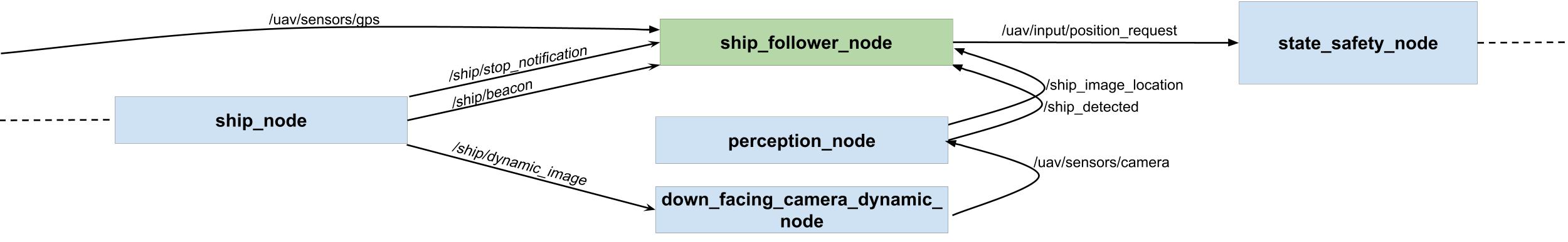
Below is a simplified diagram showing the core nodes involved in this lab. The green node is to be developed, the blue ones are provided. A ship_node simulates data that would be generated by a ship, including a rendering of it in the environment. Images are processed by the perception package of the drone. The location data from ship_node and image data from perception are then used for by your node ship_follower_node to produce control inputs to the state_safety_node.
The skeleton code is provided in simple_control/src/ship_following_controller.py:
#!/usr/bin/env python
import rospy
import time
import math
import numpy as np
from threading import Lock

from geometry_msgs.msg import Vector3, PoseStamped
from std_msgs.msg import String, Bool
from sensor_msgs.msg import Image
from sensor_msgs.msg import Image
from cv_bridge import CvBridge

from pid import PID

# A class used to follow ship below drone
class ShipFollower():
  # On node initialization
  def __init__(self):
    # Init the x and y pid params

    # Init the x and y PIDs

    # Init distance epsilon

    # Init class vars
    self.pos = Vector3()
    self.pos.x = 0.0
    self.pos.y = 0.0
    self.pos.z = 9.0

    # Create the publishers and subscribers
    self.position_pub = None# TODO
    self.mainloop()

  def get_stop(self, msg):
    pass

  # Subscribe to the current GPS data
  def get_gps(self, msg):
    pass

  # TO DO FOR CHECKPOINT 1
  # callback for /ship/beacon
  def get_ship_distance(self, msg):
    pass

  # TO DO FOR CHECKPOINT 1
  # callback for /ship_image_location
  # convert center of mass from x,y offset in pixels from top left corner of image
  # to x,y offset from center of image
  def get_image_distance(self, msg):
    pass

  # callback for downfacing camera
  def get_image(self, msg):
    pass

  def mainloop(self):
    # Set the rate of this loop
    rate = rospy.Rate(4)

    # Publish (0,0,9) to start to help find the ship
    self.position_pub.publish(self.pos)

    # While ROS is still running
    while not rospy.is_shutdown():
      # Call the PIDs

      # Publish the position


      # Sleep for the remainder of the loop
      rate.sleep()


if __name__ == '__main__':
  rospy.init_node('ship_follower_node')
  try:
    ktp = ShipFollower()
  except rospy.ROSInterruptException:
    pass
To implement your PIDs, skeleton code for a reusable PID class is provided.
#!/usr/bin/env python

class PID():
  # TODO FOR CHECKPOINTS 1-3
  # On node initialization
  def __init__(self, p=0.0, i=0,0, d=0,0):
    pass

   # TODO FOR CHECKPOINTS 1-3
  def pid_loop(self, error, dt):
    pass
Add the ship_follower_node and the ROS parameters to the fly.launch file.
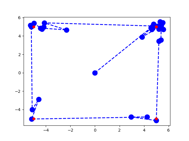
A script has been provided for you in src/simple_control/src/debug_pid.py to visualize the behavior of your PID as it traverses four waypoints arranged in a square. The output of this script is shown below. The red dots show the expected waypoints, while the blue dots show the drone’s position at set time intervals. You can see how the drone would traverse by looking at the blue dotted lines.
This is an opportunity for you to tune a PID in a simplified (but still noisy) environment and see some of the behaviors that certain kinds of tuning produce (overshoot, oscillation, etc.). Feel free to change the waypoint configuration or dt of the PID loop to figure out how your PID approaches setpoints, but keep in mind that the tuning for this PID is not necessarily going to translate to your drone. The purpose of this script is for you to be able to test your PID implementation independent of the rest of the system and gain a general understanding of what PID behavior looks like as it relates to its tuning.
What Should We Test and How Should We Test it?
Assuming that your code builds and your launched files are changed, now comes the time to check if it all works according to the requirements.
In Lab 4, we checked the correctness of the classes we developed using unit test with Python unittest. For testing classes or groups of classes that rely on ROS, such as those nodes subscribing and publishing, we need to integrate the tests within rostest. Rostest provides you with a wide range of built-in capabilities to test your code. For example, rostests include a family of predefined tests such as hztest to check that topics are published at the correct frequency, the paramtest which tests that parameters are set correctly, and the publishtest that tests if specific topics are published at least once. In addition to the non-functional tests, rostest allows you to create custom test classes that can be tailored to your specific application. We have developed a few such test cases for you in the system_tests package. These tests will run the system and validate that the communication between nodes and node integration works as expected, and you will develop similar tests to check your ship_follower_node.
Configure rostest
Rostest is already installed on your VM. To signal to catkin that the package system_test contains tests, we have made some changes to package.xml and CMakeLists.txt. To package.xml of the system_test package we added the line:
<test_depend>rostest</test_depend>
This indicates that your tests rely on the package rostest. To CMakeLists.txt of the system_test package we added the lines:
find_package(rostest REQUIRED)

add_rostest(launch/hz_test.launch)
add_rostest(launch/param_test.launch)
add_rostest(launch/test_p_hovering.launch)
Recall that the CMakeLists.txt tells catkin how to build your ROS code. By adding these lines, you indicate to catkin that it should compile the tests hz_test.launch, param_test.launch, and test_p_hovering.launch.
Ros HZ Tests
Let’s start with some of the most basic tests. The first tests we will generate and validate that the nodes are publishing at the expected frequency. Such rates are important as they directly affect the controller’s performance. Consider a person driving a car. The person continuously collects sensor information and makes micro-adjustments to the steering and throttle at a really high rate (say 100Hz). Now imagine the catastrophic results if that person was only allowed to take snapshots of the world once every second (1Hz). Similarly, imagine what would happen if we told the person they were only allowed to update the steering and throttle once every second (1Hz). The same catastrophic results would occur with PIDs that are not operating at the required rate.
To test that the topic messages are being published at the correct rates, we can use what is known as an hztest test. These tests take in four parameters:
topic: The topic you want to monitorhz: The expected frequency of the topichzerror: The amount of allowed errortest_duration: The duration of the test.
Now let’s take a look at how these test files are written. Open the system_tests/launch folder. Inside the folder, you will find hz_test.launch. Let’s analyze it using what we already know.
  <test test-name="gps_hztest" pkg="rostest" type="hztest" name="gpsHZ" >
    <param name="topic" value="uav/sensors/gps" />
    <param name="hz" value="100" />
    <param name="hzerror" value="10" />
    <param name="test_duration" value="10.0" />
  </test>
Here we can see that we have created a test that monitors the topic uav/sensors/gps with an expected frequency of 100hz, that can vary between 90hz:110hzas per the hzerror. This test will run for 10 seconds.
You can run the test using
$ rostest system_tests hz_test.launch

[ROSTEST]-----------------------------------------------------------------------

[system_tests.rosunit-gps_hztest/test_hz][passed]

SUMMARY
 * RESULT: SUCCESS
 * TESTS: 1
 * ERRORS: 0
 * FAILURES: 0
Here you can see that the first GPS test passed.
Your task now is to create similar tests that check each of the following topics meets the required frequency:
- The ships beacon topic:
/ship/beacon- (Required 4Hz) - The topic that describes when a ship is detected:
/ship_detected- (Required 2Hz) - The topic that contains the camera data:
/uav/sensors/camera- (Required 5Hz) - The topic that outputs your PID commands:
/uva/input/position_request- (Required 4Hz)
Next, assign what you would consider an acceptable error. Make sure you can explain why you selected the acceptable error.
Ros Param Tests
Another basic test type that we should write checks whether the parameter server is set as you expect. There are occasions when you forget to set or poorly set a parameter in a launch file, which leads to unexpected and potentially dangerous consequences. For example, consider forgetting to set the P term of your controller. Your controller would not work as expected and might publish control commands that result in the robot crashing.
These tests are known as paramtests. In our lab, we will simply be checking if the value of the parameter is not empty. We can see that this test checks that the virtual cage parameters are not empty. There are rostests that offer richer semantics, like testing for specific values using param_value_specific. We will not use them in this lab; however, more information on them can be found here.
Look at the param.launch file. You will see the following code:
  <test pkg="rostest" type="paramtest" name="paramtest_nonempty" test-name="paramtest_nonempty">

    <param name="param_name_target" value="/state_safety_node/virtual_cage/x" />
    <param name="param_name_target" value="/state_safety_node/virtual_cage/y" />
    <param name="param_name_target" value="/state_safety_node/virtual_cage/z" />

    <param name="test_duration" value="5.0" />
    <param name="wait_time" value="5.0" />
  </test>
Note that the test executes for 5.0 seconds using the test_duration parameter. The parameters are read and validated after 5.0 seconds using the wait_time parameter. By waiting 5 seconds before reading the parameter server, you make sure that you have given your system enough time to start up and for the parameter server to be fully populated.
You can run the test using
$ rostest system_tests param_test.launch

[ROSTEST]-----------------------------------------------------------------------

[system_tests.rosunit-paramtest_nonempty/test_param][passed]

SUMMARY
 * RESULT: SUCCESS
 * TESTS: 1
 * ERRORS: 0
 * FAILURES: 0
Here you can see that the test passed.
Your task now is to update the above example to check that your PID parameters are not empty.
Checkpoint 1
Showcase your updated hztest and paramtest.
- Do all you tests pass? If not, why?
- What did you select as an acceptable error bound in the
hztest? - If you were to create
param_value_specifictests what would you have created?
More Advanced ROS Tests
We will now be developing full tests for our PID controllers based on the skeleton tests we have provided.
Writing functional tests is slightly more complicated than using the predefined hztest and paramtest. To create these functional tests, we will need to develop our own custom test class. We will then launch the system as well as our custom test class, and it will subscribe to different topics and validate system behavior through a series of assert statements. rostest will still work as a test execution framework, printing out a summary of the process as well as whether any asserts failed and for what reasons.
Let’s start with the sample test_p_hovering.launch test file.
<?xml version="1.0"?>
<launch>

  <include file="$(find flightcontroller)/launch/fly.launch">
    <arg name="ship_velocity" default="0.1" />
    <arg name="ship_waypoints" default="[[0, 0]]" />
    <!-- TODO: Update px-->
    <arg name="px" default="0.00" />
    <arg name="ix" default="0.00" />
    <arg name="dx" default="0.00" />
    <!-- TODO: Update py-->
    <arg name="py" default="0.00" />
    <arg name="iy" default="0.00" />
    <arg name="dy" default="0.00" />
    <arg name="logging" default="log" />
  </include>

  <node name="debug_print_node" pkg="system_tests" type="print_node.py" output="screen"/>

  <test test-name="test_p_hovering" pkg="system_tests" type="drone_behavior_test.py" time-limit="120.0">
    <param name="duration" type="double" value="30.0" />
  </test>

</launch>
First, you will notice that this test launch file starts by launching the system using fly.launch. Recall that we run our code using roslaunch flightcontroller fly.launch. By including this launch file into our test launch, we can start the system that we want to test.
The first argument sets the ship_velocity. The second gives the ship_waypoints. We then provide the PID parameters. (Right now, they are all set to 0, you will need to update these values to the values you found for your system). We then set the logging parameter to log (instead of screen) to free up the terminal so we can more easily read screen messages printed during our testing process.
The next node we include is the debug_print_node. This is a custom node we have provided to you that subscribes to a topic /test_debug and prints it to the terminal. We need to do this as ROS tests cannot print to the terminal. Thus if we want to print to the terminal to debug our test cases we can now publish a String message to the /test_debug topic and it will be printed to screen for us.
Finally, we invoke our test test_p_hovering, described in the drone_behavior_test.py file inside the system_tests package. This test has a time-limit of 120 seconds. We pass it a single parameter called duration that defines the duration of each of the individual tests we perform. Thus we could perform a total of 4 tests within our time-limit.
The test file drone_behavior_test.py checks two properties:
test_following: This validates that once the ship is seen, it is always seen and never lost.test_ship_within_expected_range: This validates that at the end of the test, the drone and the ship are aligned.
If you open the file drone_behavior_test.py you will find the following:
class TestDroneBehavior(unittest.TestCase):

    def __init__(self, *args):
        super(TestDroneBehavior, self).__init__(*args)
        rospy.init_node("test_behavior", anonymous=True)
        # Publish the debug information
        self.debug_logger = rospy.Publisher('/test_debug', String, queue_size=1)
        # Get the test duration
        self.test_duration = rospy.get_param(rospy.get_name() + '/duration')

    # Print the message
    def print_msg(self, incoming_data):
        msg = String()
        msg.data = str(incoming_data)
        self.debug_logger.publish(msg)

    # Once the ship is seen, it is never unseen
    def test_following(self):
        self.print_msg("Starting: test_following")
        # TODO: Update this function to check that once a ship is detected, it is never lost.
        # Get the start time
        start_time = time.time()
        # Test for a set duration
        while time.time() - start_time < self.test_duration:
            # Get the ship detected message
            detected = rospy.wait_for_message("/ship_detected", Bool, timeout=None)
            # Edit assert statement to make sure we never un-detect the ship
            self.assertEqual(detected.data, False, "Lost contact of the ship before test_duration")
            rospy.sleep(0.1)

    def test_ship_within_expected_range(self):
        self.print_msg("Starting: test_ship_within_expected_range")
        # TODO Update this function to use dxdy to compute the distance between the ship and the drone.
        # TODO then check that it is within 50 pixels
        # Use a rolling average of window 10
        # Get the start time
        start_time = time.time()
        # Get the distance to the ship
        while time.time() - start_time < self.test_duration:
            # Compute euclidian distance
            dxdy = rospy.wait_for_message("/ship_image_location", Vector3, timeout=None)
            rospy.sleep(0.1)
        # Test at the end its within expected distance
        self.assertTrue(True, "Ship is not within 50 pixels after test_duration")


if __name__ == '__main__':
    rostest.rosrun("system_tests", "drone_behavior_test", TestDroneBehavior, sys.argv)
The file declares the class TestDroneBehavior which inherits from unittest. In our testing class’s initialization, we create a publisher that publishes string messages on the topic /test_debug. Next we get the duration parameter passed into the class by the launch file.
We then declare a function print_msg that publishes the data passed to it on the topic /test_debug. This function will allow us to print to the terminal by calling self.print_msg("message we want to print").
Next comes the first custom test test_following.
Your task: parts of this test have been removed, and you will need to implement them. As the test stands, it records the start time, and then loops for the test_duration specified as a parameter. During this time it listens to messages on the /ship_detected topic. It then checks whether the data is equal to False. Your job will be to change this test so that once the ship has been detected on the ship_detected topic, you assert that it never becomes undetected. Hint: you will need to and add additional logic and change the assert statement.
The second custom test is described in test_ship_within_expected_range. Similar to the first test, it will require some development to test the required specifications. As it stands, it loops for the duration of the test. Inside the loop we listen to the /ship_image_location topic. Your task: update this test to validate that the ship is within a 50 pixel threshold after the 30 seconds.
Remember that sensors are noisy and so we require you use a window of size 10 to store the distance values. Then use the average of those last 10 readings to get a more accurate final reading.
Once you have updated the test, you can use the rosttest command to run them. Both tests should eventually pass as shown below:
$ rostest system_tests test_p_hovering.launch
[INFO] [...]: Starting: test_following
[INFO] [...]: Starting: test_ship_within_expected_range
...
[ROSTEST]-----------------------------------------------------------------------

[system_tests.rosunit-test_p_hovering/test_following][passed]
[system_tests.rosunit-test_p_hovering/test_ship_within_expected_range][passed]

SUMMARY
 * RESULT: SUCCESS
 * TESTS: 2
 * ERRORS: 0
 * FAILURES: 0
Testing a P-Controller
At this point, you should have your src/simple_control/src/ship_following_controller.py and src/simple_control/src/pid.py completed and a good understanding of the provided testing infrastructure.
To test the p-controller, set the px and py terms, and leave the rest as zero.
Add/change values for the P portion of the controller using the px and py params in fly.launch.
When the P-controller is tuned, you should be able to identify some overshoot, undershoot, and/or oscillation around the points being set.
Between tests, you may find it useful to change the P params using rosparam set.
Given the previous two properties (1: at the end of the test, the drone should be within 50 pixels of the ship, and 2)once the ship is visualized, the drone never loses sight of the ship), develop 3 tests that check that the system meets those properties under the following conditions:
-
Scenario1: The ship is stationary (Given to you)
-
Scenario2: The ship moves in a straight line
-
Scenario3: The ship moves in a zigzag (hint: it probably won’t pass).
Remember, for scenarios 2 and 3 you will need to create a launch file for each test scenario. You will also need to add the tests to the CMakeList.txt so that ROS compiles them.
In order for your tests to be considered passing, you are required to use the same P, I, and D values for all of the tests and scenarios within a checkpoint.
Checkpoint 2
Showcase your tests working for the PID controllers P term.
-
Showcase your drone passing all developed tests (except the last one)
-
If scenario 3 fails, why does it fail?
-
Create a new publisher in
ship_follower_nodeto publish a Vector3 on the topicship/estimated_position, that estimates the ship’s position. Using rqt_plot, show the x and y of the estimated ship position inuav/sensors/gpsalongside the x and y ofuav/input/position_request.
Testing a PD-Controller
At this point, the px and py params are mostly tuned, the dx and dy params are being tuned, and ix and iy params are zero.
When the PD-controller is tuned, you should be able to see a reduction in oscillation from your previous P-controller tests.
Add/change values for the D portion of the controller using the dx and dy params in fly.launch. Once you have tuned the D terms and think your controller is working, develop two tests that confirm this. The test will use the same specifications as we used earlier for Checkpoint 1. The two tests which should be developed are:
-
Scenario4: The ship is stationary with the PD parameters set.
-
Scenario5: The ship moves in a spiral (hint: it probably won’t work well)
Once you have created your new test, make sure to rerun your new controller with your new P and D values on all the test scenarios from checkpoint 1 and these new ones.
Checkpoint 3
Showcase your drone working for the PID controllers D term.
-
Showcase your drone working when the ship is stationary, the ship moves in a straight line, and the ship is moving in a zigzag.
-
Does your spiral test case pass or fail? Why?
Testing a PID-Controller
At this point, all that’s left to tune is the I term. The I term exists to scale the accumulated error to meet the setpoint more quickly. Tune the ix and iy params. Once you are sure you have tuned the I term, develop two tests to showcase it.
-
Scenario6: The ship is stationary with the PID parameters set.
-
Scenario7: The ship moves at high-speed to randomly placed waypoints (hint: it probably won’t work well)
Checkpoint 4
Showcase your drone working for the PID controllers I term.
-
Showcase your drone running all tests from checkpoint 2 and 3, as well as moving at high-speed to randomly placed waypoints.
-
Does the high-speed test fail? If so why?
-
How might the I term account for a constant outside force exerted on the drone, such as gusts of wind? How might a P or PD controller act under the same circumstances?
Congratulations, you are done with Lab 6!
Final Check:
- Showcase your updated
hztestandparamtest.- Do all you tests pass? If not, why?
- What did you select as an acceptable error bound in the
hztest? - If you were to create
param_value_specifictests what would you have created?
- Showcase your tests working for the PID controllers P term.
- Showcase your drone passing all developed tests (except the last one)
- If test 3 fails, why does it fail?
- Create a new publisher in
ship_follower_nodeto publish a Vector3 on the topicship/estimated_position, that estimates the ship’s position using processing of/ship/beaconand/ship_image_location. How closely do they follow each other? - Using rqt_plot, show the x and y of the estimated ship position in
uav/sensors/gpsalongside the x and y ofuav/input/position_request. How quickly does/uav/sensors/gps
- Showcase your tests working for the PID controllers D term.
- Showcase your drone working when the ship is stationary, the ship moves in a straight line, and the ship is moving in a zigzag.
- Does your spiral test case pass or fail? Why?
- Showcase your tests working for the PID controllers I term.
- Showcase your drone running all tests from checkpoint 2 and 3, as well as moving at high-speed to randomly placed waypoints.
- Does the high-speed test fail? If so why?
- How might the I term account for a constant outside force exerted on the drone, such as gusts of wind? How might a P or PD controller act under the same circumstances?